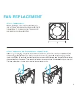
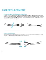
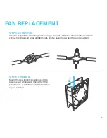
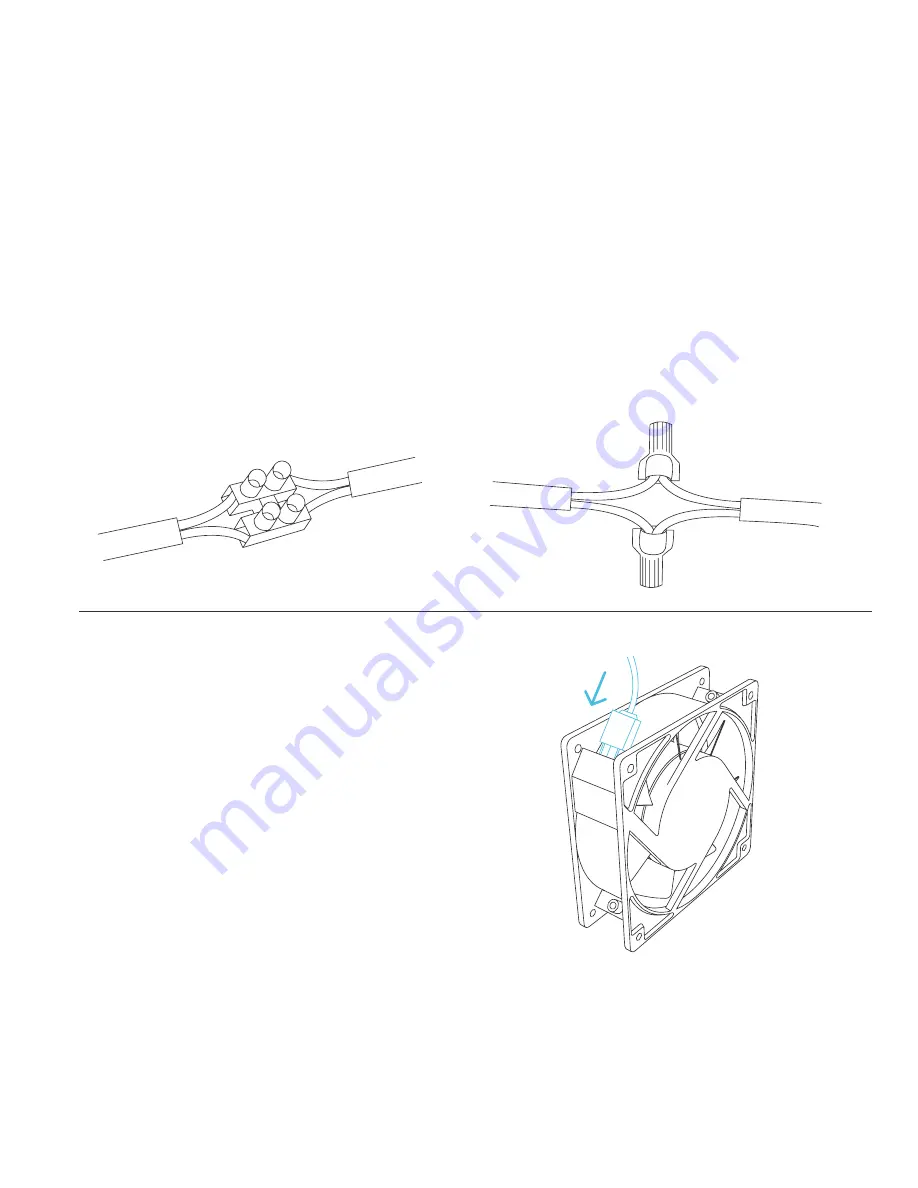
background image

11

FAN REPLACEMENT

STEP 4 - CONNECTING

You can connect the two wire pairs by using a connect or block or electrical tape and wire 
connectors. Exposed wires and terminals can be hazardous when the fan is powered.

STEP 5 - TERMINALS

Mount the new fan into position using the 
previous fan’ s hardware. Then attach the 
power cord’s connectors onto the terminals 
of your new fan.

Summary of Contents for 819137020078

Page 1: ...USER MANUAL USER MANUAL AXIAL SERIES PROJECT COOLING FANS ...

Page 2: ......

Page 3: ...roduct quality and friendly customer service If you have any questions or suggestions please don t hesitate to contact us Visit www acinfinity com and click contact for our contact information EMAIL support acinfinity com WEB www acinfinity com LOCATION Los Angeles CA ...

Page 4: ...5D AXIAL S1238 AXIAL S1238D AXIAL LS1238 MODEL HS8025A X LS8038A X HS9225A X HS9238A X LS1225A X HS1238A X HS1751A X AI 120SCX AI 120SCXD AI 1238SCX AI 1238SCXD LS1238A X UPC A 854759004259 854759004273 854759004228 854759004266 854759004211 854759004181 854759004303 854759004129 854759004150 819137020078 819137020085 819137020542 ...

Page 5: ...ual Index Fan Specifications Key Features Product Contents Fan Replacement Mounting Powering Speed Controller Other AC Infinity Products Warranty Page 5 Page 6 Page 7 Page 8 Page 9 Page 12 Page 15 Page 16 Page 17 Page 18 ...

Page 6: ...ave terminal or wires as its power connector located on the edges of its case Terminals are two metal prongs which can be attached to a cord such as a power plug Wire connectors also known as leads are directly wired to the power source SPEED Some applications demand a high airflow while others require minimal noise To meet these requirements fans are available in different speeds rated in RPM or ...

Page 7: ...meet UL 94 standards for resistance to flammability DUAL BALL BEARINGS Long life bearings rated at 67 000 hours Also allows the fan to be mounted in any direction SPEED CONTROLLER Allows control of the fans speed and the ability to adjust the fans airflow and noise level for various applications AC VOLTAGE Rated between 100 to 125V AC the fan can be powered directly by a US household outlet withou...

Page 8: ...38A X AI 120SCX AI 120SCXD AXIAL 9225 AXIAL 9238 AXIAL LS1238 HS9225A X HS9238A X LS1238A X AI 1238SCX AI 1238SCXD LS1225A X HS1238A X HS1751A X AXIAL FAN x1 FAN GUARDS x2 SCREWS x4 HINGE x1 SPEED CONTROLLER x1 AXIAL FAN x1 AXIAL FAN x2 FAN GUARDS x2 FAN GUARDS x4 SCREWS x4 SCREWS x8 POWER CORD x1 M H L SPEED CONTROLLER x1 M H L HINGE x2 ...

Page 9: ...ECTORS If the fan you are trying to replace has terminal connectors detach its power connector from the terminals by pulling it off the fan If the connectors cannot be pulled off please see page 10 for more information on previous fan that has wired connectors Mount the new fan into position using the previous fan s hardware Then attach the power connectors onto the terminals of your new fan Turn ...

Page 10: ... cut the wire to remove the previous fan Then take the power plug cord included in this kit and remove the head with a wire stripper Under the cords plastic should be two identical wires with their tips exposed STEP 3 WIRING LEADS The previous power source should have a set of two wires Connect one wire from the plug cord to one wire on the power source then repeat for the second pair ...

Page 11: ... connect or block or electrical tape and wire connectors Exposed wires and terminals can be hazardous when the fan is powered STEP 5 TERMINALS Mount the new fan into position using the previous fan s hardware Then attach the power cord s connectors onto the terminals of your new fan ...

Page 12: ...a hole saw onto the power drill create the center hole as outlined by your markings from the previous step The hole saw size is dependent on the fan s case size Using a power drill create four screw holes as outlined by your markings from the previous step We recommend using a drill bit size from 10 64 to 14 64 Please see page 14 for Hinge Mounting Instructions for Speed Control Fan Kits ...

Page 13: ...he fan s side and another guard on the opposite end while keeping the screw holes aligned STEP 4 MOUNTING Mount the unit using four machine screws while holding each corresponding nut in place Use a screwdriver to finish tightening the unit securely Please see page 15 on instructions on powering the fan ...

Page 14: ...ately STEP 2 MOUNTING HINGE To mount the hinge on to your setup use the included wood screw to drill into position You may need to turn the hinge to its side to create a clear pathway to mount the wood screws through the hinge and onto a surface Please see page 15 on instructions on powering the fan Hinges are only included with Speed Control Fan Kits S1225 S1225D S1238 and S1238D ...

Page 15: ...astly plug the cord s head into a standard outlet You may also power the fan with a wired power source please see page 10 and 11 STEP 1 TERMINAL After mounting your fan you can then attach the power plug cord onto the fans terminal ...

Page 16: ...hen keep turning until the fan is at full power OFF To completely shut off the fan keep turning the knob counter clockwise until you feel a click SPEED CONTROL To adjust the fan s speed first turn the knob clockwise and the fan speed will increase gradually from low to high Then slowley turn it counter clockwise to lower the speed or to turn off the fan M H L Controller is sold separately only inc...

Page 17: ...re a thermal trigger and speed control T Series features a LCD digital display with thermal and speed control alarm alerts failure triggers and backup memory PRODUCT AIRPLATE S1 AIRPLATE S3 AIRPLATE S5 AIRPLATE S7 AIRPLATE S9 PRODUCT AIRCOM S6 AIRCOM S7 AIRCOM S8 AIRCOM S9 AIRCOM T8 AIRCOM T9 MODEL AI CFS80BA AI CFS120BA AI CFD80BA AI CFD120BA AI APS9 MODEL AI ACS6 AI ACS7 AI ACS8 AI ACS9 AI ACT8 ...

Page 18: ... during that period AC Infinity will replace your product with a new one or issue you a full refund The warranty program does not cover abuse or misuse This includes physical damage submersion of the product in water incorrect Installation such as wrong voltage input and misuse for any reason other than intended purposes AC Infinity is not responsible for consequential loss or incidental damages o...

Page 19: ......

Page 20: ...www acinfinity com ...

Reviews: