background image

27

TIMER ALERT

Flashes when a countdown has completed for TIMER TO ON, TIMER TO 
OFF, CYCLE, or SCHEDULE Mode.

DISPLAY LOCK ALERT

Displays when you lock the controller. The icon will flash and beep if you 
attempt to adjust the controller while it is still locked. 

LOW HUMIDITY ALARM

Flashes and beeps with an alert if the humidity falls below the trigger point 
set in the app. Continues to flash until the humidity rises above the trigger 
point. 

BLUETOOTH

Appears when the physical controller is connected to the app via Bluetooth. 

CHECK FAN ALERT

Flashes when the fan's probe senses interference to its functioning. Check 
the fan for possible issues. If the fan is not working, please see the warranty 
page for replacement information. 

PROGRAMMING

Summary of Contents for 819137020900

Page 1: ...USER MANUAL USER MANUAL AIRLIFT SERIES SHUTTER EXHAUST FAN SYSTEM ...

Page 2: ......

Page 3: ...roduct quality and friendly customer service If you have any questions or suggestions please don t hesitate to contact us Visit www acinfinity com and click contact for our contact information EMAIL support acinfinity com WEB www acinfinity com LOCATION Los Angeles CA ...

Page 4: ... AC ALT22 AC ALT30 AC ALT36 UPC A 819137021433 819137021440 819137021457 819137021464 819137020900 819137020917 819137020924 819137020948 819137020948 819137020955 819137020962 819137020986 819137020993 MANUAL CODE AL2104X1 SERIOUS INJURY OR DEATH Please do not touch the fan s impeller and blades Secure all nearby objects including wires and cables from coming into contact with the fan s impeller ...

Page 5: ...dex Key Features Product Contents Installation Powering and Setup Daisy Chain and Setup Programming Other Settings Other AC Infinity Products Warranty Page 5 Page 6 Page 7 Page 8 Page 11 Page 14 Page 15 Page 28 Page 30 Page 31 ...

Page 6: ...PROOF The shutter fan unit is sealed to Ingress Protection 44 standards to be resistant to liquid and dust DUAL BALL BEARINGS Long life bearings rated at 67 000 hours Also allows the fan to be mounted in any direction EFFICIENT EC MOTOR PWM controlled EC motor enables precise speed control low noise and higher energy efficiency SPEED CONTROLLER Single button controller with circular readout displa...

Page 7: ... SCREWS WALL MOUNT x2 WOOD SCREWS WALL MOUNT x2 MACHINE SCREWS SHUTTER MOUNT x4 WIRE TIES x4 WOOD SCREWS SHUTTER MOUNT x4 AIRLIFT T SERIES SENSOR PROBE x1 SMART CONTROLLER x1 WOOD SCREWS WALL HANG x2 WOOD SCREWS WALL MOUNT x2 MACHINE SCREWS WALL MOUNT x2 SHUTTER FAN UNIT x1 ...

Page 8: ...ed higher in the room to exhaust out heated air which will rise on its own due to natural convection STEP 2 Measure the dimensions of the shutter fan s mounting frame which will go through the wall Select a location on the wall where you will be mounting the fan Please make sure that the wall is free of any wires or pipes Using the measurements of the shutter fan use a level and ruler to draw an o...

Page 9: ... fan unit Then using a drill bit create the four mounting holes STEP 3 Depending on your mounting surface material use the appropriate tools to cut into the wall Use a drill or a hand saw to create an opening large enough to insert a saw blade or jigsaw inside the outlined area of the wall panel Thinner Woods or Plastic Woods Tougher Plastic or Metal ...

Page 10: ...cure the fan If you are using your own shutter remove the AIRLIFT s shutter by unscrewing the nuts and bolts from the fan guard Reassemble the fan guard onto your existing shutter by reapplying the nuts and bolts in the same mounting locations STEP 6 Once the fan is mounted securely you can then mount the controller using the included hardware Place the controller near the fan in order to power th...

Page 11: ...P 2 Plug the fans power cord into an AC power outlet to power the fan and controller STEP 1 Plug the shutter fan s 4 pin Molex connector into the speed controller s port at the top POWERING AND SETUP S SERIES ...

Page 12: ... preferably in the hottest area of the room You can use the wire tie to secure the probe away from the fan blades STEP 1 Locate the connector plug of the sensor probe and plug it into the bottom of the thermal controller POWERING AND SETUP T SERIES ...

Page 13: ...13 POWERING AND SETUP STEP 4 Plug the fans power cord into an AC power outlet to power the fan and controller STEP 3 Connect the Molex end from the fan into the bottom of the controller T SERIES ...

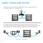
Page 14: ...elow is for T Series model only The controller included is compatible with AC Infinity fan models that contain an EC motor Typically EC motor fans will have a separate cord coming out of it for the power and the controller The compatible fans do not need to be the same model or part of the same product series EC Motor Compatible ...

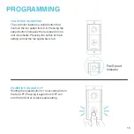
Page 15: ...peed button increases the fan speed in one unit increments Pressing the button at the 8 setting will set the fan speed back to 0 POWERING ON AND OFF Holding the speed button for 4 seconds will turn the fan OFF Pressing it again from OFF will turn the fan ON at its last speed setting Fan Speed Indicator PROGRAMMING ...

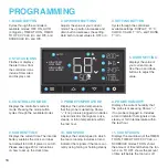
Page 16: ...modes TO ON shows the amount of time left before the fan turns on TO OFF shows the amount of time left before the fan turns off 9 CURRENT TIME Displays the current time The internal battery sustains the clock so it does not default to 00 00 if power is cut off Please see page 23 for instructions on how to set up the clock time 7 PROBE TEMPERATURE Displays the current temperature that the probe is ...

Page 17: ...s it will instead run at the speed set here AUTO MODE HIGH TEMPERATURE TRIGGER Pressing the up or down button sets the high temperature trigger The fans will activate if the probe s reading meets or exceeds this threshold Once triggered the fan will gradually ramp up to the speed set in ON mode If the probe s reading falls below this trigger point the fans will gradually slow down to a stop or at ...

Page 18: ...robe s reading meets or exceeds this threshold Once triggered the fan will gradually ramp up to the speed set in ON mode If the probe s reading falls below this trigger point the fans will gradually slow down to a stop or at the speed set in OFF mode You may set this trigger below the low humidity trigger to create a specific range in which the fan is active Note that this trigger can activate as ...

Page 19: ...wn time Once the timer ends the fans will trigger to run at the speed set in ON Mode If there is a speed set in OFF Mode the fans will run at that speed during the countdown The countdown will begin if no buttons are pressed for 5 seconds The time left on the countdown is displayed below the current fan speed Leaving the timer mode while the countdown is running will pause it until you return to t...

Page 20: ...y Press the up or down button to first set a duration for the fan to activate Then press the mode button again and set a duration for the fan to deactivate When the fan is activated it will run at the speed set in ON Mode When the fan is deactivated it will run at the speed set in OFF Mode The countdown will begin if no buttons are pressed for 5 seconds The time left on the countdown before the ne...

Page 21: ...te it will run at the speed set in ON Mode When the fan is triggered to deactivate it will run at the speed set in OFF Mode The countdown will begin if no buttons are pressed for 5 seconds The time left on the countdown before the next on or off phase is displayed below the current fan speed The fan will not follow this schedule if you leave this mode If you re enter the Schedule Mode it will cont...

Page 22: ...gh levels 1 2 3 A2 and A3 3 being the highest brightness setting while 1 is the lowest In settings 1 2 and 3 the display will stay at that brightness level and will not automatically dim the display A2 and A3 will set the brightness level at 2 and 3 respectively and will dim down the brightness level 1 when the controller is not being used after 15 seconds CONTROLLER SETTINGS Pressing the setting ...

Page 23: ...ION HUMIDITY SETTING Adjusts the relative humidity reading the sensor probe is measuring Press the up or down button to increase or decrease the data figure in 1 increments The calibration cycle ranges from 8 to 8 and will be applied to the sensor probe s measurements CLOCK SETTING Adjusts the current clock time Press the up or down button to increase or decrease the time Once you cycle through 12...

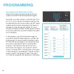
Page 24: ...peed will ramp up by one speed level up until it reaches the speed set in ON Mode In this example your high temperature trigger is set at 80 F the OFF Mode speed is 0 and the ON Mode speed is 6 If the transition threshold is set to 0 F then the fan will trigger to run at speed 6 when the sensor temperature meets or exceeds 80 F However if the transition threshold is set to 2 F then the fan will tr...

Page 25: ...ill ramp up by one speed level up until it reaches the speed set in ON Mode In this example your high humidity trigger is set at 67 the OFF Mode speed is 2 and the ON Mode speed is 7 If the transition threshold is set to 0 then the fan will trigger to run at speed 7 when the sensor temperature meets or exceeds 67 However if the transition threshold is set to 5 then the fan will trigger to run at s...

Page 26: ...PERATURE ALARM Flashes and beeps with an alert if the temperature rises above the trigger point set in the app Continues to flash until the temperature falls below the trigger point LOW TEMPERATURE ALARM Flashes and beeps with an alert if the temperature falls below the trigger point set in the app Continues to flash until the temperature rises above the trigger point HIGH HUMIDITY ALARM Flashes a...

Page 27: ...ITY ALARM Flashes and beeps with an alert if the humidity falls below the trigger point set in the app Continues to flash until the humidity rises above the trigger point BLUETOOTH Appears when the physical controller is connected to the app via Bluetooth CHECK FAN ALERT Flashes when the fan s probe senses interference to its functioning Check the fan for possible issues If the fan is not working ...

Page 28: ...oller in your cur rent mode While your controller is locked no parameters may be adjusted nor will you be able to switch modes Holding the power button again will unlock the controller HOLD HIDE SCREEN Lock the controller so no settings can be adjusted See above Then press the setting button to turn the display off Pressing it again will turn the display back on Programs will still run in the back...

Page 29: ...m HOLD HOLD HOLD BLUETOOTH RESET Hold the mode and settings buttons simultaneously for 5 seconds to clear advance programming from the controller The app will disconnect from the controller and will have to be paired again to re establish Bluetooth connection All sensor data controller programming and settings will be retained OTHER SETTINGS ...

Page 30: ... fans designed to quietly ven tilate AV rooms and closets as well as various DIY air circulation and exhaust projects Features a thermal controller with intelligent pro gramming that will automatically adjust duct fan speeds in response to changing temperatures Crawlspace Fans The AIRTITAN is a line of weather proof fans designed to provide ventilation odor and moisture control for crawl spaces an...

Page 31: ...ive malfunctioned or expressively if the product becomes unusable The warranty program goes into effect on the date of purchase The program will expire two years from the date of purchase If your product becomes defective during that period AC Infinity will replace your product with a new one or issue you a full refund The warranty program does not cover abuse or misuse This includes physical dama...

Page 32: ...No part of the materials including graphics or logos available in this booklet may be copied photocopied reproduced translated or reduced to any electronic medium or machine readable form in whole or in part without specific permission from AC Infinity Inc ...

Page 33: ......

Page 34: ......

Page 35: ......

Page 36: ...www acinfinity com ...

Reviews: