ƹ
Ƴ
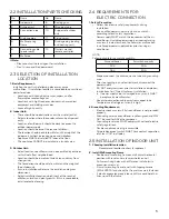
.6 INSTALLATION OF OUTDOOR
UNIT
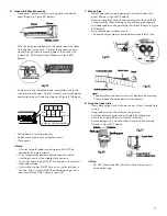
1. Support of Outdoor Unit
• Select according to actual installation situation. Select
installation location according to the structure.
• Affix outdoor unit support with expansion screws.
!
Ì
Note:
• Use personal protection equipment while performing
installation.
• Prep the outdoor unit to support up to four times the weight of
the unit.
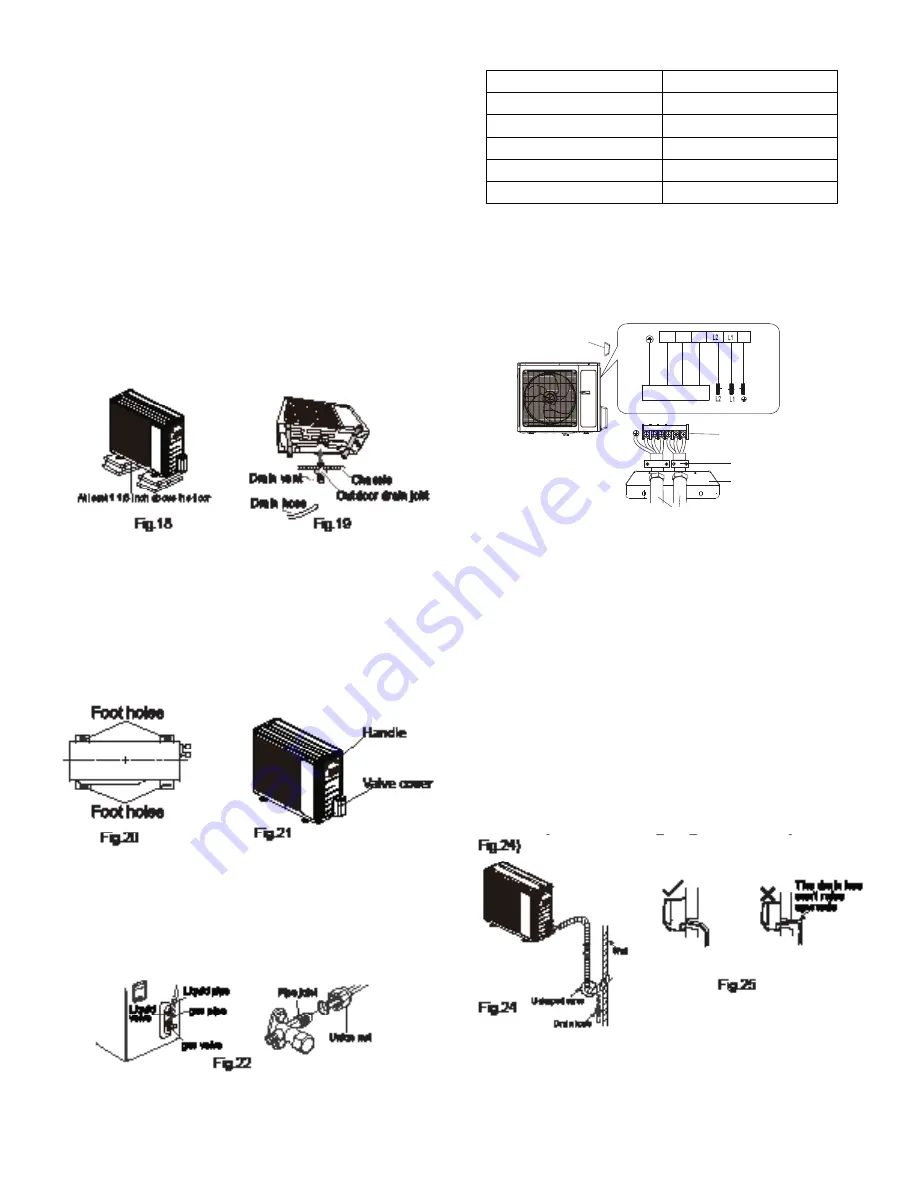
• Outdoor unit should be installed at least 1 1/16” above the floor
in order to install drain joint. (Shown in Figure #18 below).
• Six expansion screws should be used for units with cooling
capacities of 2,300W – 5,000W.
• Eight expansion screws should be used for units with cooling
capacities of 6,000W – 8,000W.
• Ten expansion screws should be used for units with cooling
capacities of 10,000W – 16,000W.
2. Install Drain Joint
•
Connect outdoor drain joint to the hole in the chassis.
•
Connect drain hose to drain vent (Shown in Figure #19
above).
3. Outdoor Unit
•
Place outdoor unit on support.
•
Affix the foot holes of the outdoor unit with appropriate
bolts. (Shown in Figure #20 below).
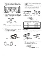
4. Connect Indoor and Outdoor Pipes
•
Remove screw on right cable cross plate sub-assy and valve
cover of outdoor unit then remove the cable cross plate sub-
assy and valve cover (Shown in Figure #21 above).
•
Remove the screw cap of valve and aim the pipe joint at the
bellmouth of pipe (Shown in Figure #22 below).
•
Pretighten the union nut by hand.
•
Tighten the union nut with torque wrench. Refer to table
below.
Refer to the following table for wrench moment of force:
Hex nut diameter(inch)
Tightening torque(ft·Ibf)
ĭ
1/4
11.10~14.75
ĭ
3/8
20.12~29.50
ĭ
1/2
33.19~40.56
ĭ
5/8
44.24~47.94
ĭ
3/4
51.32~55.31
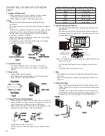
5. Connect Outdoor Electric Wire
•
Insert power connection wire and power wire through wire-
passing hole.
•
Remove wire clip and connect the power connect wire and
the power wire to wiring terminal. Affix with screws (Shown
in Figure #23 below).
Note: The wiring connect is for reference only,please refer to the
actual one. Fig.23
• Affix
the
power
connection wire and power wire with wire
clip.
• Install the cable cross plate sub-assy.
!
Ì
Note:
• After tightening the screw, pull the power cord slightly to check
if it is firm.
• Never cut the power connection wire to prolong or shorten the
distance.
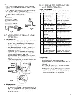
6. Neaten the Pipes
• Pipes should be placed along the wall, reasonably bent and
hidden if possible. Minimum semi-diameter of bending pipe
is 4 inches.
• If outdoor unit is higher than wall hole, set U-shaped curve
in pipe before inserting into wall hole in order to prevent rain
from getting in the room (Shown in Figure #24 below).
Handle
Indoor unit connection
Power
G
L1'
white
(blue)
white
(blue)
green
(yellow-green)
green
(yellow-green)
red
(brown)
black
(brown)
black
S
L2'
L1'
L2' L2 L1 G
S
Wiring board
Wire clip
Retaining Plate
Note: the wiring connect is
for reference only,please
refer to the actual one.
)LJ


