background image

Ƹ

6. Indoor 

Unit 

Wire 

Connection

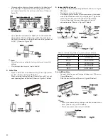
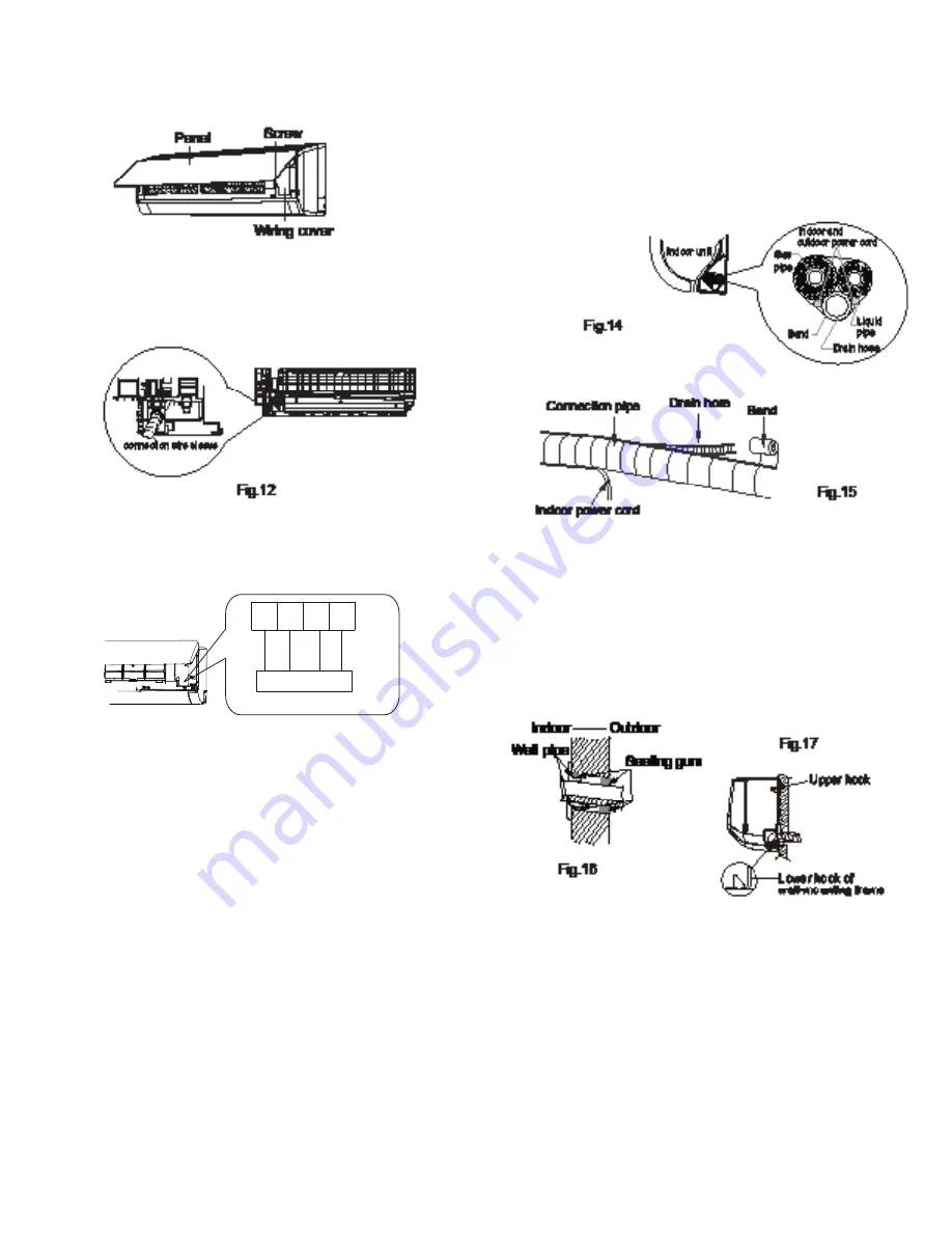
•  Open panel.  Remove screw on wiring panel and detach

cover (Shown in Figure #11 below).

Affix the wire crossing board on the connection wire sleeve 
to the bottom of the case.  Position the connection wire 
sleeve through the wire crossing hole at the back of the 
indoor unit.  Pull through front (Shown in Figure #12 
below).

•  Remove wire clip.  Attached power connection wire to the 

wiring terminal by color.  Tighten screw(s) and attach power 
connection wire with wire clip (Shown in Figure #13 below).

•  Wiring board is for reference only.
•  Replace wire cover back and tighten screw.
• Close 

panel.

!

Ì

Note:

•   All wires for both indoor and outdoor units MUST be 

connected by a professional.

•   If the length of the power supply connection cable is 

insufficient, contact the supplier for a new one.

•   Units that contain plugs MUST have plugs in convenient/

reachable location.

•   Units without plugs MUST have an air switch installed in

the line.  The air switch MUST be all-pole parting and the
contact distance MUST be more than 1/8”.

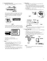
7. Bind up Pipe

Bind the connection pipe, power cord and drain hose with
band.  Shown in Figure #14 below).

•  Reserve a length of drain hose and power cord for installation

during binding.  When binding to a specific degree, separate 
the indoor power and separate the drain hose (Shown in Figure 
#15 below).

•  Bind all cordage and hoses evenly.
•  The liquid and gas pipes should be bound separately at the 

end.

!

Ì

Note:

•  The power cord and control wire cant be crossed or winding.
• The drain hose should be bound at the bottom.

8. Hang the Indoor Unit

Insert bound pipes in to wall pipe and pass them through hole 
in wall.

•  Hang indoor unit on the wall mounting frame.
•  Stuff gap between pipes and wall hole with sealing gum.
•  Affix the wall pipe (Shown in Figure #16 below).

Ensure indoor unit is close to the wall and installed securely 
(shown in Figure #17 below).

!

Ì

Note:

• DO NOT excessively bend the drain hose. Doing so may 

cause a blockage.

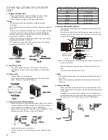
outdoor unit connection

white
(blue)

black

red

(brown)

L1'

S L2'

G

green
(yellow-green)

Summary of Contents for AWH30LB-D3DNA3D/I

Page 1: ...AC Pro S Series 30 36K àøĀ ØØ ĀÅæà Manual Models AWH30LB D3DNA3D I AWH30LB D3DNA3G O AWH30LB D3DNA3D I AWH36LB D3DNA3G O Refrigerant R410A ...

Page 2: ...We reserve the right to correct any clerical errors Copyright 2018 AC Pro ...

Page 3: ...vered they MUST be repaired replaced by qualified technician 10 If the power cord or power connection wire is not long enough replace with specialized cable from manufacturer before proceeding with installation or repair DO NOT elongate these wires 11 An air switch MUST be installed if there is no plug found on the air conditioner The air switch MUST be all pole parting and the contact parting dis...

Page 4: ... drill drill head electric drill 4 Electroprobe 5 Universal meter 6 Torque wrench open end wrench inner hexagon spanner 7 Electronic leakage detector 8 Vacuum pump 9 Pressure meter 10 Pipe pliers pipe cutter 11 Pipe expander pipe bender 12 Soldering appliance refrigerant container essure meter ...

Page 5: ...ƴ Ƴ 0 INSTALLATION Ƴ 1 Installation Dimension Diagram 6SDFH WR WKH REVWUXFWLRQ ...

Page 6: ... pipes and hang the indoor unit Install the support of outdoor unit select it according to the actual situation Fix outdoor unit Make the bound pipes pass through the wall hole and then connect outdoor unit Install drainage joint of outdoor unit only for cooling and heating unit Connect pipes of outdoor unit Connect wires of outdoor unit Neaten the pipes Vacuum pumping and leakage detection Check ...

Page 7: ...s is unavoidable install protective fencing Ƴ 4 REQUIREMENTS FOR ELECTRIC CONNECTION 1 Safety Precaution Follow ALL electric safety requirements during installation Use qualified power supply circuit and air switch according to local safety regulations Power supply MUST match the requirement of the air conditioner Unstable power supply or incorrect wiring may result in electric shock fire hazard o...

Page 8: ...ing hole on bottom Shown in Figures 4 below 5 Indoor Unit Pipe Connect Aim pipe to the corresponding bellmouth Shown in Figure 5 below Pre tighten union nut by hand Use following torque table as reference below Use double wrench technique on union nut and pipe joint Tighten the union nut with torque wrench Shown in Figure 6 Use insulation tape to wrap indoor pipe and joint of connection pipe Shown...

Page 9: ...ir switch installed in the line The air switch MUST be all pole parting and the contact distance MUST be more than 1 8 7 Bind up Pipe Bind the connection pipe power cord and drain hose with band Shown in Figure 14 below Reserve a length of drain hose and power cord for installation during binding When binding to a specific degree separate the indoor power and separate the drain hose Shown in Figur...

Page 10: ...th of pipe Shown in Figure 22 below Pretighten the union nut by hand Tighten the union nut with torque wrench Refer to table below Refer to the following table for wrench moment of force Hex nut diameter inch Tightening torque ft Ibf ĭ1 4 11 10 14 75 ĭ3 8 20 12 29 50 ĭ1 2 33 19 40 56 ĭ5 8 44 24 47 94 ĭ3 4 51 32 55 31 5 Connect Outdoor Electric Wire Insert power connection wire and power wire throu...

Page 11: ...OPERATION 1 Check after Installation Check according to the following requirement after finishing installation No Items to be checked Possible malfunction 1 Has the unit been installed firmly Unit may shake or emit rattling noise 2 Was refrigerant leakage test performed This may cause insufficient cooling heating capacity 3 Is heat insulation of pipeline sufficient May cause condensation and water...

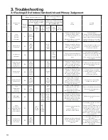
Page 12: ...erload 5 Overcurrent Protection E5 OFF 3s and blink 5 times Always ON During cooling and drying operation compressor and outdoor fan stop while indoor fan operates During heating operation all loads stop 1 Supply voltage is unstable 2 Supply voltage is too low and load is too high 3 Evaporator is dirty 6 Communication Malfunction E6 OFF 3s and blink 6 times OFF 1S and blink 6 times During cooling ...

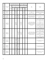
Page 13: ...emperature sensor is open short circuited F3 OFF 3S and blink 3 times OFF 1S and blink 6 times During cooling and drying operating compressor stops while indoor fan operates During heating operation the complete unit will stop operation Outdoor temperature sensor hasnt been connected well or is damaged Please check it by referring to the resistance table for temperature sensor 15 Outdoor condenser...

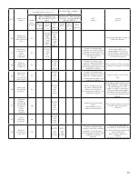
Page 14: ... board XT if the voltage is higher than 265VAC turn on the unit after the supply voltage is increased to the normal range 2 If the AC input is normal measure the voltage of electrolytic capacitor C on control panel AP1 if its normal theres malfunction for the circuit please replace the control panel AP1 22 Voltage of DC bus bar is too low PL OFF 3S and blink 21 times OFF 1S and blink 12 times Duri...

Page 15: ...alfunction of module temperature sensor circuit P7 OFF 3S and blink 18 times During cooling and drying operation compressor will stop while indoor fan will operate During heating operation the complete unit will stop Replace outdoor control panel AP1 30 Module high temperature protection P8 OFF 3S and blink 19 times During cooling operation compressor will stop while indoor fan will operate During...

Page 16: ...n motor is stalling 4 Motor malfunction 5 Malfunction of mainboard rev detecting circuit 38 Desynchronizing of compressor H7 OFF 3S and blink 7 times During cooling and drying operation compressor will stop while indoor fan will operate During heating operation the complete unit will stop operation Refer to the malfunction analysis IPM protection loss of synchronism protection and overcurrent prot...

Page 17: ...l stop while indoor fan will operate During heating operating the complete unit will stop operation Theres circuit malfunction on outdoor units control panel AP1 please replace the outdoor units control panel AP1 47 The four way valve is abnormal U7 OFF 3S and blink 20 times If this malfunction occurs during heating operation the complete unit will stop operation 1 Supply voltage is lower than AC1...

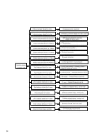
Page 18: ...ƲƷ ...

Page 19: ...cient or too much refrigrant blockage of capillary an dincrease of suction temp improper running of compressor burning in or stuck of bearing damage of discharge valve malfunction of protector Processing method adjust refrigerant amount replace the capillary replace the compressor use universal meter to check if the contactor of compressor is fine when it is not over heated if not replace the prot...

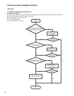
Page 20: ...Malfunction diagnosis process V WKH ZLULQJ WHUPLQDO EHWZHHQ WKH WHPSHUDWXUH VHQVRU DQG WKH FRQWUROOHU ORRVHQHG RU SRRUO FRQWDFWHG Start QVHUW WKH WHPSHUDWXUH VHQVRU WLJKWO Yes Yes Yes Yes Yes Yes No No No No No No V PDOIXQFWLRQ eliminated V PDOIXQFWLRQ eliminated V PDOIXQFWLRQ eliminated 5HSODFH LW ZLWK D WHPSHUDWXUH VHQVRU ZLWK WKH VDPH PRGHO 0DNH WKH SDUWV XSULJKW V WKHUH VKRUW FLUFXLW GXH WR WU...

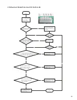
Page 21: ...sert the wiring terminal of indoor fan It s the malfunction of main board Replace a new main board that is of the same model It s the malfunction of main board Replace a new main board that is of the same model Replace a new main board that is of the same model It s the malfunction of main board Then check whether the voltage between terminal 2 and terminal 3 of the motor interface is 15VDC Connec...

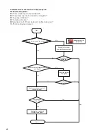
Page 22: ... is defined abnormal Malfunction diagnosis process Start V WKHUH MXPSHU FDS RQ WKH PDLQERDUG V WKH MXPSHU FDS LQVHUWHG FRUUHFWO DQG WLJKWO 5HSODFH WKH MXPSHU FDS ZLWK WKH VDPH PRGHO SSHDUDQFH RI WKH MXPSHU FDS VVHPEOH WKH MXPSHU FDS ZLWK WKH VDPH PRGHO QVHUW WKH MXPSHU FDS WLJKWO V PDOIXQFWLRQ eliminated V PDOIXQFWLRQ eliminated V PDOIXQFWLRQ eliminated 5HSODFH WKH PDLQERDUG ZLWK WKH VDPH PRGHO En...

Page 23: ... 5HSODFH WKH PDLQERDUG ZLWK WKH VDPH PRGHO End V WKH VXSSO YROWDJH WRR ORZ ZLWK RYHUORDG V WKH LQGRRU RXWGRRU KHDW H FKDQJHU GLUW RU DUH WKH DLU LQOHW DQG RXWOHW EORFNHG 7KH IDQ LV DEQRUPDO DQ VSHHG LV WRR ORZ RU IDQ GRHVQ W URWDWH 0HDVXUH WKH FXUUHQW RI OLYH ZLUH RQ WKH PDLQ ERDUG ZLWK D FODPS DPSHUH PHWHU V WKH FXUUHQW KLJKHU WKDQ WKH YDOXH RI WKH RYHUFXUUHQW SURWHFWLRQ V WKHUH EORFNDJH LQVLGH W...

Page 24: ...zero cross detection circuit of the mainboard is defined abnormal Malfunction diagnosis process 7XUQ SRZHU RII IRU PLQXWH WKH WXUQ EDFN RQ 7KH XQLW UHWXUQV WR QRUPDO RQFOXVLRQ 8 LV GLVSOD HG GXH WR SRZHU RII RQ ZKLOH WKH FDSDFLWRU GLVFKDUJHV VORZO U8 is still displayed 7KH HUR FURVV GHWHFWLRQ FLUFXLW RI WKH PDLQERDUG LV GH QHG DEQRUPDO 5HSODFH WKH PDLQERDUG ZLWK WKH VDPH PRGHO Yes No Start End ...

Page 25: ...er supply Check if connection line of IDU and ODU and the wire inside electric box are correctly connected Correct connection Main board matches with display board Main board of IDU matches with that of ODU Communication cord is damaged Replace IDU s main board Malfunction eliminated End Connect the line according to wiring diagram Match correctly according to product specification Replace communi...

Page 26: ...h the voltage testing circuit on control panel AP1 Replace the control panel AP1 Measure the AC voltage between terminalL andN on wiring board XT power supply Voltage within 210VAC 250VAC Shut down the power and repair the power supply to restore the range 210VAC 250VAC power on and restart the unit If the fault is eliminated Shut down the power and wait 20 minutes or use DC voltmeter to measure t...

Page 27: ...he system pressure is too high and exceeds the permissible range 4 If the charge volume of refrigerant is too much resulting in that the system pressure is too high 5 Other conditions resulting in that the system pressure becomes too high Take corrective actions according to Technical Service Manual and then energize and start the unit If there is any abnormality described above Replace the contro...

Page 28: ... Overheat and high temperature protection Is outdoor ambient temperature higher than 53 20 minutes after the complete unit is powered off Is heat dissipation of the indoor unit and outdoor unit abnormal Normal protection please operate it after the outdoor ambient temp erature is normalized Improve the heat dissipation environ ment of the unit Does the outdoor fan work normally 1 Check if the fan ...

Page 29: ...pressor stopping enough Y N Y N N Y Y N Power on the unit Is stop time of the compressor longer than 3 minutes Restart it up after 3 minutes Does startup fail Are the wires for the compressor connected correctly Is connection sequence right Connect the wires as per the connection diagram Replace the control panel AP1 If the fault is eliminated Replace the compressor End ...

Page 30: ...res for the compressor connected correctly Is connection sequence right Is the connection made in clockwise direction Connect the wires correctly Replace the control panel AP1 If the fault is eliminated Replace the compressor End Out of step occurs in operation Is the outdoor fan working normally Is the outdoor unit blocked by foreign objects Replace the control panel AP1 If the fault is eliminate...

Page 31: ...plete unit is powered off Is the terminal FA for the electronic expansion valve connected correctly Connect the wires correctly Resistances between the first four pins close to the terminal hole and the fifth pin are almost the same less than 100 ohm Replace the electronic expansion valve If the fault is eliminated If the fault is eliminated Replace the control panel AP1 Coolant leakage refilling ...

Page 32: ...he reactor L of the outdoor unit and the PFC capacitor Whether there is any damage or short circuit Replace it as per the wiring diagram and reconnect the wires If the fault is eliminated Disconnect the terminals for the reactor and measure the resistance between the two terminals of the reactor by an ohm gauge Whether there is any damage or short circuit Replace the reactor Restart the unit If th...

Page 33: ...e failure occurs The AP1 voltage detection circuit is at fault Check wiring inside of the indoor and outdoor units Are wires broken Check the communication circuit of the outdoor unit If the fault is eliminated The communication circuit is abnormal Replace the main board of the indoor unit End If the fault is eliminated Replace the main board AP1 of the outdoor unit If the fault is eliminated Is t...

Page 34: ...e normally before the failure occurs The AP1 voltage detection circuit is at fault Check wiring inside of the indoor and outdoor units Are wires broken Check the communication circuit of the outdoor unit If the fault is eliminated The communication circuit is abnormal Replace the main board of the indoor unit End If the fault is eliminated Replace the main board AP1 of the outdoor unit If the faul...

Page 35: ...ly open Check if the capacity output of outdoor unit is equal to the capacity demand of indoor units Check if the indoor outdoor filters or radiating fins are dirty or blocked Clean the fins The system pipe is blocked Refer to the dial up of indoor and outdoor unit Measure the swing motor and signal input Measure the fan motor and signal input Remove the obstructions Cover up the front panel prope...

Page 36: ... unit and outdoor unit is improper Check whether the installation postion is proper according to installation requirement for air conditioner Adjust the installation position and install the rainproof and sunproof for outdoor unit Refrigerant is leaking Discharged air temperature during cooling is higher than normal discharged wind temperature Discharged air temperature during heating is lower tha...

Page 37: ...inder of compressor is blocked Compressor cant operate Repair or replace compressor 6 Air Conditioner is Leaking Possible Causes Discriminating Method Air conditioner Status Troubleshooting Drain pipe is blocked Water leaking from indoor unit Eliminate the foreign objects inside the drain pipe Drain pipe is broken Water leaking from drain pipe Replace drain pipe Wrapping is not tight Water leaking...

Page 38: ...ƴƷ Ƶ EXPLODED VIEW AND PARTS LIST Ƶ 1 Indoor Unit ...

Page 39: ...2051 1 21 Left Evaporator Support 24212041 24212041 1 22 Evaporator Assy 01002000027 01002000027 1 23 Wall Mounting Frame 01252398 01252398 1 24 Right Support of Evaporator 2421204201 2421204201 1 25 Fan Motor 1501213401 1501213401 1 26 Pipe Clamp 26112071 26112071 1 27 Drainage Hose 0523001404 0523001404 1 28 Fixed Clip Evaporator 02112009 02112009 1 29 Cover Plate 20122124 20122124 1 30 Motor Fi...

Page 40: ...ƴƹ AWH30LB D3DNA3G 0 AWH36LB D3DNA3G 0 2 6 7 8 9 10 11 12 13 14 15 16 17 18 19 20 21 22 23 24 25 26 27 28 29 30 31 32 33 34 35 36 37 38 39 40 41 4 5 3 1 ...

Page 41: ...02113109 02113109 1 19 Wiring Clamp 26115004 26115004 1 20 Electronic Expansion Valve Sub Assy 07133688 07133688 1 21 Temperature Sensor 3900031001 3900031001 1 22 Rear Grill 01475013 01475013 1 23 Condenser Assy 01163509 01163491 1 24 Clapboard 01233134 01233134 1 25 Condenser Support Plate 01175092 01175037 1 26 Motor Support Sub Assy 0180287601 01802876 1 27 Top Cover Sub Assy 01255007 01255007...

Page 42: ... Procedure of Indoor Unit Steps Procedure 1 Before disassembly of the unit axonometric drawing for the complete unit 2 Remove Filter 1 2 3 Open the Panel Loosen the clasps on the filter Draw out two pieces of filter panel clasps filter ...

Page 43: ...isplay and then remove the filter 4 Remove Panel Pull the clasps at both sides slightly and then remove the panel 5 Remove Horizontal Louver Remve the axial bush on the horizontal louver and then remove the horizontal louver display clasp panel horizontal louver ...

Page 44: ... screws fixing the top cover of electric box Remove the top cover of electric box 7 Remove Front Case 1 2 3 Remove the screw caps on front case Remove screws connecting the front case Remove the Front case screw top cover of electric box screw cap screw front case ...

Page 45: ...ove earthing screws and then remove the earthing wire 9 Remove elextric box cover 1 2 3 Loosen clasps at the left side of electric box Lossen clasps on the right side of elec tric box Remove electric box cover screw clasp clasp electric box cover ...

Page 46: ... 10 RemoveTemperature Sensor Pull out the indoor temperature sensor 11 Remove Electric Box 1 2 3 Pull out 6 sockets on PCB board Pull out two scews on electric box Remove electric box temperature sensor screw electric bo ...

Page 47: ...n pipe between indoor and outdoor units 14 Remove pipe stopping plate Remove two scews on pipe stopping plate for indoor unit and then remove the pipe stopping plate 15 Remove damping board Remove 2 screws on damping board and then remove the damping board water tray connection position for indoor and outdoor units connection pipe pipe stopping plate screw screw damping board ...

Page 48: ...se Turn over the indoor unit and adjust the pipe line to the position as shown by the broken line Lift up the evaporator and then remove the evaporator 17 Remove the fixing plate of motor Remove 2 screws on fixing plate of motor and then remove the fixing plate of motor screw evaporator screw ...

Page 49: ...ƵƸ Steps Procedure 18 Remove cross flow blade and motor 1 2 3 Remove screws fixing cross flow blade and motor Remove the motor sub assy Seperate two cross flow blade blade motor ...

Page 50: ...Ƶƹ Steps Procedure 19 Remove cusion rubber 1 2 Remove the cushion rubber on cross flow blade Remove the cusion rubber from the base cushion rubber ...

Page 51: ...e and then remove valve cover Remove the screws connecting the top cover with outer case right side plate and left side plate lift the top cover upwards to remove it 2 Remove front side panel Loosen the screws connecting the front side panel and chassis Remove the front side panel Ì Warning Be sure to wait for a minimum of 20 minutes after turning off all power supplies and discharge the refrigera...

Page 52: ...ssis and motor support with screwdriver and then remove the panel 4 Remove right side plate Twist off the screws connecting the right side plate and chassis valve sup port and condenser and then remove the right side plate 5 Remove axial flow blade Twist off the nuts on blade with wrench and then remove the axial flow blade grille panel right side plate axial flow blade ...

Page 53: ...g terminal pull it upwards to remove the electric box Twist off the screws on electric box fireproofing with screwdriver and then remove the electric box fireproof ing 7 Remove motor Twist off the tapping screws fixing the motor pull out the pin of leading wire for motor and then remove the motor electric box electric box fireproofing motor ...

Page 54: ...solation sheet Twist off the screws connecting isola tation sheet and end plate of condens er and chassis and then remove the isolation sheet 10 Remove 4 way valve Unsolder the pipeline between com pressor condenser gas and liquid valve and then remove the 4 way valve note release all refrigerant before unsoldering motor support isolation sheet 4 way valve ...

Page 55: ...et cloth com pletely to avoid the damage to valve and release all refrigerant completely at first Unsolder the soldering joint between liquid valve and connection pipe of liquid valve and then remove the liquid valve 12 Remove valve support Twist off the screws connecting valve support and chassis and then remove the valve support 13 Remove Compressor Twist off the 3 foot nuts on compressor and th...

Page 56: ...late Twist off the screws connecting the left side plate and chassis with screwdriver and then remove the left side plate 15 Remove chassis and condenser Pull it upwards to separate the chassis and condenser left side plate chassis condenser ...

Page 57: ...denser Valve Valve Liquid pipe side Gas pipe side Strainer Electron expansion valve Strainer Accumlator Compressor Connection pipe specification Liquid pipe 1 4 in Gas pipe 5 8 in Indoor unit Outdoor unit COO I H I 4 Way al e Discharge Suction Heat e changer e aporator Heat e changer condenser al e al e i uid pipe side as pipe side Strainer lectron e pansion al e Strainer ccumlator Compressor Capi...

Page 58: ...mper Cap is used to determine fan speed and the swing angle of horizontal lover for this model 3OHDVH GRQ W WRXFK DQ HOHFWURQLF FRPSRQHQW RU WHUPLQDO ZKHQ WKH PDFKLQH LV UXQQLQJ VWRSSLQJ RU KDV EHHQ SRZHUHG RII IRU OHVV WKDQ PLQXWHV WR SUHYHQW HOHFWULF VKRFN 287 225 81 7 8 5 1 1 1 7 50 1 2 5220 7 03 78 7 03 6 1625 6 1625 63 2 5 5 9 5 1 0 1 2 5 0 02725 6 1 5 21752 5 211 725 803 3 1 02725 3 6 1 8 78...

Page 59: ...1 225 81 7 7 8 5 1 6 8 32 5 02725 3 5 1 3 1 97 97 9 9 9 5 1 0 1 7 29 5 2 3527 725 1 1 9 8 57 57 57 0 5 2 1 29 203 5 6 7 203 203 8 7 03 6 1625 28778 2875220 7 03 6 1625 867 7 03 6 1625 1 1 35 17 5 8 7 2 5 5 725 8 9 20 27720 7 7 1 7 5 2035 6625 1 7 5 33 35 6685 6 7 3 3 16 21 9 9 7521 9 9 33 3 6 7 35 6685 2 2 127 0RWRU JURXQG RQO DSSOLHV WR WKH LURQ VKHOO PRWRU These Circuit diagrams are subject to c...

Page 60: ...6 Power Switch 7 High Frequency trans former 8 Interface of fan motor 9 Buzzer 10 Interface of display 11 Interface of display 12 Indoor tube temperature sensor interface 13 Ambient temperature sen sor interface 14 INterface of wired controller 15 Interface of left and right swing terminal 16 Interface of up and down swing terminal 17 Auto button 18 Interface of BMS 19 Jumper cap 20 Interface of w...

Page 61: ...or OVC COMP 7 Terminal of 4 Way Valve 12 ProtectiveTube FU101 3 Terminal ofTemp Sensor CN2 8 Electric Heater Band of Chassis HEAT2 L 13 Terminal of Ground Wire 4 High Pressure Protection Terminal HPP 9 Electric Heater Band of Compressor Heat1 L 14 Choke L 101 and L 102 5 Electronic Expansion Valve Terminal EV 10 Terminal of LiveWire 15 Terminal of Outdoor Fan OFAN DC 1 2 3 4 5 6 7 8 9 10 11 12 13 ...

Reviews: