background image

6

Installation and Maintenance

Service Manual

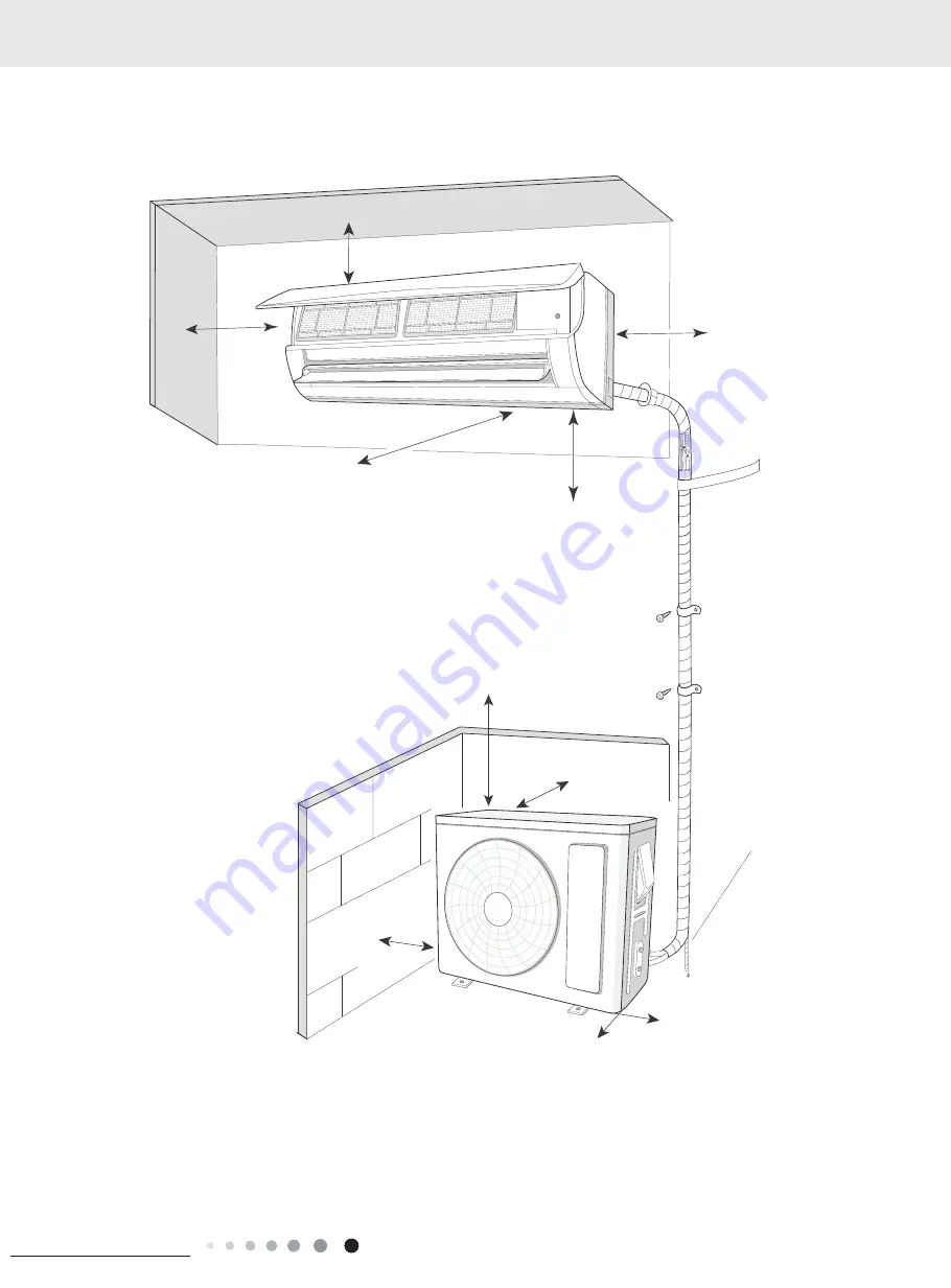
8.1 Installation Dimension Diagram

8. Installation

At least 15cm

A

At least 250cm

Space to the ceiling

t least 15cm

Space to the wall

At least 15cm

Space to the wall

At least 300cm

Space to the obstruction

Space to the floor

Drainage pipe

Space to the obstruction

At least 50cm

Space to the obstruction

At least 30cm

At least 50cm

Space to the obstruction

Space to the obstruction

At least 200c

m

Space to the wall

At least 30cm

Summary of Contents for GMS Series

Page 1: ...AC Pro GMS Series 9 12K Service Manual Models AWHD 18 ND3MO AWHD 24 ND3MO AWHD 30 ND3MO AWH09QCXD D3DNB8A I FM AWH12QCXD D3DNB8A I FM AWH18QDXF D3DNB8A I FM AWH24QEXH D3DNB8A I FM Refrigerant R410A...

Page 2: ...We reserve the right to correct any clerical errors Copyright 2018 AC pro...

Page 3: ...olong the wire by yourself 11 For the air conditioner without plug an air switch must be installed in the circuit The air switch should be all pole parting and the contact parting distance should be m...

Page 4: ...e resulting in injury 4 During refrigerant recovery make sure that liquid valve and gas valve are fully closed and power is disconnected before detaching the connection pipe If compressor starts runni...

Page 5: ...ctronic leakage detector Pipe pliers Pipe pliers Pipe cutter Screw driver Universal meter Vacuum pump Pipe bender Pipe expander Impact drill Drill head Electric drill Torque wrench Open end wrench Inn...

Page 6: ...the ceiling t least 15cm Space to the wall At least 15cm Space to the wall At least 300cm Space to the obstruction Space to the floor Drainage pipe Space to the obstruction At least 50cm Space to the...

Page 7: ...nd hang the indoor unit Make the bound pipes pass through the wall hole and then connect outdoor unit Neaten the pipes Vacuum pumping and leakage detection Check after installation and test operation...

Page 8: ...cles in 1 Please contact the local agent for installation 2 Don t use unqualified power cord Note No Name 1 Indoor unit 2 Outdoor unit 3 Connection pipe 4 Drainage pipe 5 Wall mounting frame 6 Connect...

Page 9: ...le on the bottom case As show in Fig 4 Fig 3 Left Rear left Right Rear right Fig 4 Cut off the hole Left Right 5 Connect the Pipe of Indoor Unit 1 Aim the pipe joint at the corresponding bellmouth As...

Page 10: ...take down the cover As show in Fig 11 Panel Screw Wiring cover Fig 11 2 Make the power connection wire go through the cable cross hole at the back of indoor unit and then pull it out from the front s...

Page 11: ...torque N m 1 4 15 20 3 8 30 40 1 2 45 55 5 8 60 65 3 4 70 75 5 Connect Outdoor Electric Wire 1 Remove the wire clip connect the power connection wire and signal control wire only for cooling and heati...

Page 12: ...There s a leakage 8 9 Check after Installation and Test operation 1 Check after Installation Check according to the following requirement after finishing installation NO Items to be checked Possible m...

Page 13: ...stant protection E8 During cooling operation compressor will stop while indoor fan will operate During heating operation the complete unit stops Refer to the malfunction analysis overload high tempera...

Page 14: ...ensor hasn t been inserted into the copper tube 17 Limit decrease frequency due to overload F6 All loads operate normally while operation frequency for compressor is decreased Refer to the malfunction...

Page 15: ...ease on IPM Module of outdoor control panel AP1 is sufficient and whether the radiator is inserted tightly If it s no use please replace control panel AP1 31 Overload protection for compressor H3 Duri...

Page 16: ...stop while indoor fan will operate During heating operation the complete unit will stop Supply voltage is unstable 44 Malfunction of complete unit s current detection U5 During cooling and drying ope...

Page 17: ...mainboard broken Malfunction diagnosis process Is the wiring terminal between the temperature sensor and the controller loosened or poorly contacted Start Insert the temperature sensor tightly Yes Ye...

Page 18: ...ck if the connection of PG motor control terminal is firm Turn on the unit again measure whether the output voltage on control terminal for PG motor is more than 50V within 1 min after the louvers are...

Page 19: ...mper cap tightly Is malfunction eliminated Is malfunction eliminated Is malfunction eliminated Replace the mainboard with the same model End Yes Yes Yes Yes Yes No No No No No 3 Malfunction of Protect...

Page 20: ...tordischarges slowly The zero cross detectioncircuit of the mainboard is defined abnormal Malfunction diagnosis process Turn power off for 1minute the turn back on The unit returns to normal Conclusio...

Page 21: ...tart check if the connection wire are correctly connected Replace the detecting plate with the same model Is malfunction eliminated Replace the mainboard with the same model The end Yes Yes No 5 Malfu...

Page 22: ...stem System is blocked inside dirt block ice block oil block Y valve no fully open Compressor doesn t work normally Strange noise or leakage occurs Make compressor run normally Casing is too hot Repla...

Page 23: ...ure the voltage between COM and N of the control board of outdoor unit DC notch about 56V Start Y Y Y Y Y Y Y N N N N N N If the unit is operation normal before malfunction Check connection wire of in...

Page 24: ...eplace the compressor Replace the mainboard with the same model End Is the supply voltage too low with overload Is the indoor outdoor heat exchanger dirty or are the air inlet and outlet blocked The f...

Page 25: ...voltage testing circuit on control panel AP1 Replace the control panel AP1 Measure the AC voltage between terminalL andN on wiring board XT power supply Voltage within 210VAC 250VAC Shut down the pow...

Page 26: ...orrectly connect the wires of compressor according to the electric wiring diagram and then turn on the unit Check the connection between the control board and the compressor by referring to the electr...

Page 27: ...nt temperature higher than 53 Normal protection Please operate it when the outdoor ambient temperature is improved Is the radiation of indoor unit After the complete unit is disconnected from the powe...

Page 28: ...refrigerant Malfunction diagnosis process No Yes No No Yes Yes Yes No Power on the unit Is stop time of the compressor longer than 3 minutes Restart it up after 3 minutes Does startup fail Are the wir...

Page 29: ...e outdoor fan Start to run until the power resume normal voltage Charge the refrigerant with service manual Replace compressor Remove malfunction Replace control board AP1 Connect wire well If the com...

Page 30: ...de energized for 20min N N N Y N N Replace control board AP1 End Remove malfunction Check refrigerant if there is leakage please refer to specification Remove malfunction Replace overload protector SA...

Page 31: ...he equipment operate normally before the failure occurs The AP1 voltage detection circuit is at fault Check wiring inside of the indoor and outdoor units Are wires broken Check the communication circu...

Page 32: ...pansion valve damaged If the refrigerant is leaked The compressor overload protection terminal is not connected well with the mainboard If the overload protector is damaged Heat exchange of unit is no...

Page 33: ...vice manual Compressor overload protection terminal is not connected well with the mainboard reconnect them correctly Heat exchange of unit is not good heat exchanger is dirty and unit radiating envir...

Page 34: ...details Malfunction of compressor Compressor can t operate Refer to point 5 of maintenance method for details 9 3 Troubleshooting for Normal Malfunction 1 Air Conditioner can t be Started Up 2 Poor Co...

Page 35: ...place drain pipe Wrapping is not tight Water leaking from the pipe connection place of indoor unit Wrap it again and bundle it tightly 5 Compressor can t Operate Possible causes Discriminating method...

Reviews: