background image

29

For more cool Wattage products visit our website at http://watt-age.globalhobby.com

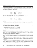
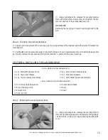
Step 4:  Applying the Decals

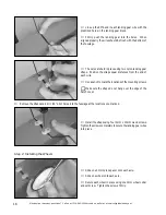
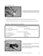
Using a clean cloth, wipe the airframe down completely to remove dust, debris and oil.

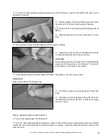
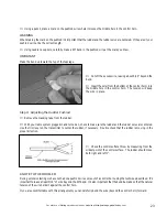
Cut out each of the decals and apply them using the box cover photos for reference.

If any air bubbles form under the decals you can "prick" the bubbles with a pin to release the air.

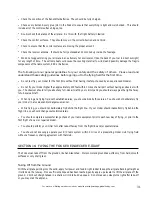
# 1 Phillips Head Screwdriver

Ruler

SECTION 13:  BALANCING

YOU'LL NEED THE FOLLOWING SUPPLIES:

Masking Tape

IMPORTANT

It is critical that your airplane be balanced correctly.  Improper balance will cause your airplane to lose control and crash!

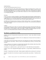
Center of Gravity Location:

2-1/2" back from the leading edge of the wing, at the fuselage sides.

WARNING

This location is recommended for initial test flying.  The C.G. can be moved fore or aft up to 1/4", but it is not
recommended that the C.G. be located any farther back than 2-3/4".

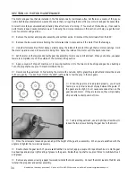
Balance the Fokker with the flight battery 

installed.

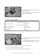
Install the wing and cockpit deck onto the fuselage.

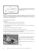
Apply two pieces of masking tape onto the 

bottom

 of the wing, 2-1/2" back from the leading edge, at the fuselage

sides.

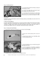
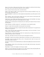
Place your fingers on the masking tape, and carefully lift the airplane.  If the nose of the airplane falls, the airplane is

nose heavy.  To correct this, move the battery pack and/or receiver  back far enough to bring the airplane into balance.  If
the tail of the airplane falls, the airplane is tail heavy.  To correct this, move the battery pack and/or receiver forward
enough to bring the airplane into balance.  When balanced correctly, the airplane should sit level or slightly nose down
when you lift it up with your fingers at the C.G. location.

Once you have flown and become familiar with the flight characteristics of the airplane,  the C.G. can be moved fore

or aft up to 1/4" in each direction to change the flight performance.  Moving the C.G. back will cause the airplane to be
more responsive, but less stable.  Moving the C.G. forward will cause the airplane to be more stable, but less responsive.

Do not fly the airplane beyond the recommended balance range or an uncontrollable crash could
result!

Summary of Contents for Fokker Eindecker E.III ARF

Page 1: ...as information about flying clubs in your area whose membership includes qualified instructors If there is no hobby shop in your area we recommend that you contact the AMA at the address below They will be able to help you locate a flying field near you Academy of Model Aeronautics 5151 East Memorial Drive Muncie IN 47302 9252 800 435 9262 www modelaircraft org Specifications Wing Area 340 square ...

Page 2: ... or material used for final assembly no liability shall be assumed for any damage resulting from the use by the user of the final user assembled product By the act of using the final user assembled product the user accepts all resulting liability Safety Warning 2 Introduction 3 Our Recommendations 4 Tools and Supplies Required 4 Kit Contents 5 Metric Conversion Chart 5 Replacement Parts 6 A Note A...

Page 3: ...9 Fax 714 964 6236 E mail service globalhobby net INTRODUCTION Thank you for purchasing the new Wattage Fokker Eindecker E III ARF Before completing the final assembly of your new airplane please carefully read through this instruction manual in its entirety Doing so will ensure success the first time around The original Fokker Eindecker was the first monoplane of WWI It was considered the technol...

Page 4: ...Eindecker These suggestions are not set in stone but they should provide you with a good starting point OUR RECOMMENDATIONS TOOLS AND SUPPLIES REQUIRED If you already have a radio system Hitec 555 Micro Receiver Hitec RX Crystal P N 444227 Cirrus CS 21 Micro Servos 2 P N 128484 Wattage IC 15A ESC P N 128522 Wattage 8C 600Mah NiCD Flight Battery P N 130103 Wattage 1 amp AC DC Peak Charger P N 86902...

Page 5: ...se contact us below AIRFRAME ASSEMBLIES 1 Fuselage w Motor Gear Box 1 Cockpit Deck 1 Right Wing Half 1 Left Wing Half 1 Horizontal Stabilizer w Elevator 1 Vertical Stabilizer w Rudder 1 Molded Cowl PUSHROD ASSEMBLIES 2 1mm x 445mm Pushrod Wires 2 Plywood Control Horns KIT CONTENTS Wattage Customer Service 18480 Bandilier Circle Fountain Valley CA 92728 Phone 714 963 0329 Fax 714 964 6236 E mail se...

Page 6: ... If the color layer smears from any of the seams the temperature of the iron is too hot Turn the temperature dial down and wait about 5 minutes for the iron to adjust to the lower temperature You can remove any excess color streaks using a paper towel soaked with a small quantity of Acetone A NOTE ABOUT COVERING Wattage stocks a complete line of replacement parts for your Fokker Eindecker ARF List...

Page 7: ...r workbench Charge the flight battery using your peak charger following the instructions that were provided with the charger Also make sure that the batteries in your transmitter are fully charged Step 2 Breaking In the Motor Set the motor assembly between the handles of a pair of needle nose pliers and secure the motor to the handles using three rubber bands This will keep the motor secure enough...

Page 8: ...ck to turn off the motor With the motor turned off test the operation of the servos Each should move when you move the control stick Carefully spray a couple of light sprays of Performance Plus Motor Spray inside the motor openings and apply a small drop of Trinity Break In Drops onto each of the two motor bushings and onto the two gear box bushings Using a couple of paper towels wipe off the exce...

Page 9: ... YOU LL NEED THE FOLLOWING SUPPLIES Rubbing Alcohol NHP Epoxy Mixing Sticks NHP Epoxy Mixing Cups Step 1 Installing the Hardwood Dowel Using a modeling knife cut away and remove the excess covering material that overlaps onto the root ribs of each wing panel After removing the covering the root ribs should look like this IMPORTANT Glue does not stick well to covering material For the stron gest jo...

Page 10: ...y together there should be few or no gaps between the two So the wing halves are not twisted it s important to make sure the leading and trailing edges of both halves line up with each other Mix a generous amount of 5 minute epoxy Apply a thin layer of epoxy to the exposed half of the hardwood dowel and to the entire surface of both root ribs Make sure to use enough epoxy to fill any gaps Be caref...

Page 11: ...uselage The C A will strengthen the threads WARNING Allow the C A to thoroughly cure before mounting the wing Secure the wing into place using one 4mm x 20mm flange head machine screw Don t overtighten the screw You don t want to crush the wing Set the wing into the wing saddle and align it The plywood tab in the leading edge of the wing should fully engage the forward bulkhead and the predrilled ...

Page 12: ...Stabilizer Remove the elevator and hinges from the stabilizer and set them aside Using a pencil draw two centerline marks on top of the stabilizer one at the leading edge and one at the trailing edge The bottom of the stabilizer has the covering removed to match the mounting platform on the fuselage Set the stabilizer onto the fuselage Line up the two centerline marks on the stabilizer with the ce...

Page 13: ...lace look from the front of the airplane at both the wing and the stabilizer When aligned properly the stabilizer should be parallel with the wing IMPORTANT If the stabilizer is out of alignment remove it and use 220 grit sandpaper with a sanding block to sand down the higher side of the stabilizer mounting platform then reinstall the stabilizer and check the alignment once more Repeat this proced...

Page 14: ...ng the Vertical Stabilizer Remove the rudder and hinges from the stabilizer and set them aside Set the vertical stabilizer into place To align it properly the rear edge of the stabilizer should be even with the rear edge of the fuselage and the stabilizer should be pushed down firmly Lining up the trailing edge of the vertical stabilizer with the back of the fuselage will prevent the rudder from i...

Page 15: ...hecking all of your measurements once more before the epoxy sets up Quickly remove the excess epoxy and hold the stabilizer in place until the epoxy has set up 1 Phillips Head Screwdriver Excel Modeling Knife Electric Drill 1 16 Drill Bit YOU LL NEED THE FOLLOWING PARTS 2 Prebent Main Gear Wires 2 Main Gear Wheels 2 Nylon Landing Gear Straps SECTION 6 INSTALLING THE LANDING GEAR 4 3mm x 10mm Wood ...

Page 16: ...osition the straps equal distances from the end of each wire Use a pencil to mark the locations of the mounting screws Make sure the straps do not hang over the edge of the hatch cover Remove the straps and drill 1 16 pilot holes into the fuselage at the locations you marked Install the straps using four 3mm x 10mm wood screws Tighten the screws completely to secure the landing gear wires into pla...

Page 17: ...knife carefully remove the covering from over the control horn mounting slot in the elevator The covering has been slit at the factory You just need to remove the excess WARNING Be careful not to cut through the covering on the opposite side IMPORTANT Before gluing the control horn into place you will need to cut a notch in the front of the control horn to clear the elevator joiner wire Apply a be...

Page 18: ...ts in the trailing edge of the stabilizer Adjust the elevator so that its tips are even with the tips of the stabilizer While holding the elevator tight against the stabilizer pivot the elevator down about 45º and apply 5 6 drops of thin C A to the exposed area of each hinge Turn the fuse lage over and repeat for the other side of the hinges Remove any C A that may run down the hinge line using C ...

Page 19: ... and rudder servos Make sure to install the collets with the flanges toward the bottom of the servos Set the servos into the servo tray taking note of their locations and the positions of the servo output shafts The sides of the servos should be pushed against the edges of the tray IMPORTANT Run the servo leads out toward the front of the airplane While holding the servos in place drill 1 16 pilot...

Page 20: ...tand Ruler Pencil Masking Tape Using a pair of Z Bend pliers make a Z Bend in one end of one pushrod wire Using a modeling knife remove all but one arm from a small 4 point servo horn The remaining arm should have at least four holes in it Using a modeling knife remove the covering material from over the elevator pushrod exit hole The hole is on the right side of the fuselage 2 in front of the rud...

Page 21: ...G When making the mark on the pushrod it s important that the elevator and the elevator servo are centered If they aren t your pushrod will not be the correct length Cut off the excess wire leaving about 5 16 beyond the bend Insert the wire from the outside of the control horn into the outermost hole in the control horn The tension will keep the wire in place Using needle nose pliers carefully mak...

Page 22: ... a pair of Z Bend pliers make a Z Bend in one end of the pushrod wire Using a modeling knife remove all but one arm from a small 4 point servo horn The remaining arm should have at least four holes in it Insert the Z Bend into the third hole out from the center of the arm Make sure the longer portion of the pushrod wire is toward the top of the servo arm Using a modeling knife remove the covering ...

Page 23: ...lace Step 4 Adjusting the Rudder Pushrod Remove the masking tape from the rudder With your radio system plugged in and turned on check to make sure the rudder and the rudder servo are centered Use the trim lever on the transmitter to center the rudder if necessary Double check that the rudder is moving in the proper direction Check the control surface throw by measuring from the widest point of th...

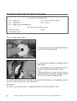
Page 24: ...push it into the spinner backplate Slide the spinner backplate and the propeller onto the propeller shaft Thread the machine screw and washer into the front of the adaptor and tighten them against the propeller Make sure that when you install the propeller that it is centered between the two molded pins otherwise the spinner cone will not line up properly with the backplate Slide the plastic spinn...

Page 25: ...ess firmly around the top of the cowl to secure it to the fuselage Kwik Bond Thick C A 1 Phillips Head Screwdriver Excel Modeling Knife Electric Drill YOU LL NEED THE FOLLOWING PARTS 1 Cockpit Deck 1 Plywood Cockpit Mounting Block 1 Pilot Figure SECTION 11 INSTALLING THE COCKPIT DECK 1 Machine Gun 1 3mm x 16mm Flange Head Wood Screw YOU LL NEED THE FOLLOWING SUPPLIES 1 16 Drill Bit Ernst Airplane ...

Page 26: ...he block down firmly IMPORTANT Because of slight differences with wing joining you may need to trim the inside edges of the mounting block to fit firmly over the plywood tabs When satisfied with the fit remove the block Using a modeling knife remove the covering material from the wing where the block glues into place Glue the plywood block into place using thick C A Allow the C A to thoroughly cur...

Page 27: ...ION 12 FINAL ASSEMBLY 1 Decal Set YOU LL NEED THE FOLLOWING SUPPLIES 5 64 Drill Bit Ernst Airplane Stand Ruler Scotch Tape Step 1 Installing the Receiver Plug the elevator and rudder servo leads into their proper slots in the receiver Mount the receiver to the fuselage floor in front of the servo tray using a piece of double side tape not included Drill a 5 64 hole through the fuselage floor next ...

Page 28: ...the Bullet Connectors on the motor leads Remember though that you may experience current loss through any style of connector If you would like to minimize current loss we suggest removing the Bullet Connectors and soldering the leads together without the connectors If soldering the leads together make sure to insulate them using heat shrink tubing or electrical tape Step 3 Installing the Flight Ba...

Page 29: ...ll the wing and cockpit deck onto the fuselage Apply two pieces of masking tape onto the bottom of the wing 2 1 2 back from the leading edge at the fuselage sides Place your fingers on the masking tape and carefully lift the airplane If the nose of the airplane falls the airplane is nose heavy To correct this move the battery pack and or receiver back far enough to bring the airplane into balance ...

Page 30: ...tion of the throttle To do this do the following A Plug in your flight battery and turn on the radio system WARNING Do not turn the receiver on unless the transmitter is turned on first Always turn the transmitter on first Never allow hands or clothing to get in the way of the propeller when the radio is turned on Sudden unwanted radio signals or turning the radio on with the throttle stick set at...

Page 31: ...aving an observer with you The observer should tell you about any full size aircraft in your vicinity and you should always give the right of way to full scale aircraft When flying at a flying field with established rules you should abide by those rules You should not deliberately fly your model in a reckless and or dangerous manner While flying you should not deliberately fly behind the flight li...

Page 32: ...fingers at the C G location Hold the airplane above shoulder level and turn on the motor to full power With the motor running at full power firmly toss the airplane straight ahead and level Do not throw it up at an angle or throw it hard Let the airplane fly straight and level to pick up airspeed then climb to your desired altitude Be careful not to climb too steeply after hand launching or you co...

Page 33: ...rt of the radio system that receives the signals from the transmitter Rudder The rudder is the control surface on the back of the airplane that moves right and left This causes the nose of the airplane to yaw right and left Servo The part of the radio system that produces the movement necessary to move the control surfaces The servo includes a small motor gears and a circuit board Servo Reversing ...

Page 34: ...h to prevent premature wear and to ensure that you re getting the most from your motor and gear box assembly All electric motors accumulate dust dirt and grime after hours of running If too much of this builds up it can lead to performance loss and cause premature wear Following the simple procedures in this section will help you get the most out of your motor and gear box Remove the spinner and p...

Page 35: ...ct our Customer Service Department to resolve the problem Yes No 7 Was any of the assembly difficult for you If yes please explain Yes No ________________________________________ ________________________________________ ________________________________________ ________________________________________ 8 What did you like most about this kit Assembly Manual Parts Fit Hardware Supplied Price Other __...

Page 36: ... Fold along dotted line Fold along dotted line Global Hobby Distributors Attn Customer Service 18480 Bandilier Circle Fountain Valley CA 92728 8610 Post Office will not deliver without proper postage _____________________________ _____________________________ _____________________________ Return Address Here ...

Reviews: