7085 NW 46
th
Street, Miami, FL 33166 - USA. Telephone: 305-8058533 Fax: 305-8058535
PI 3300 Page # 33
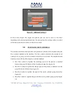
but also so that it does not contact the guide rails upon extension or retraction (see
Figure 25).
e)
Set the guide rails so that there is roughly 1/16
th
in. to 1/8 in. of clearance on each
side of the container to prevent the containers from getting stuck as they travel down
the conveyor. (See Figure 25).
f)
Adjust the distance between each nozzle, centering them over the mouths of the
containers.
g)
Place the entry cylinder in the free space between the last container that entered the
filling area, and the first container to enter the machine on the next cycle. The height
should be adjusted similar to the exit cylinder.
h)
If there is any kind of container instability, consider installing additional guide rails at
different heights to combat container movements.
iii.
Adjusting the Optical Sensors At The Entry And Exit Of The Machine
a)
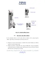
Place the entry sensor centered on the front of the body of the last container that
entered the filling area. If this sensor does not detect the container, the machine will
not initiate the fill cycle (See Figure 26).
b)
Place the exit sensor on the outside of the exit gate, at a distance roughly one bottle
width from the exit cylinder (See Figure 26).
c)
The fiber optic sensors may need to have the intensity adjusted, a delay set on the
activation, etc. If the machine does not seem to be working properly.
d)
Each container has a different set point for the fiber optic sensors. The reason for this
is because of the types of materials, different material colors, the speed of the
production line, the various sizes of containers, etc.


