background image


7085 NW 46

th

 Street, Miami, FL 33166 - USA.   Telephone: 305-8058533    Fax: 305-8058535 

www.acasi.com


PI 3300 Page # 36 


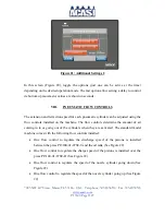
Figure 27: Adjusting Filling Volume. 


XII.


HOW THE MACHINE WORKS 


For  the  description  below  we  will  assume  that  the  machine  will  be  setup  using  the 

“Down” type fill cycle, and with just one stroke per fill cycle. 


a)


When  the  air  feed  for  the  machine  is  connected,  the  nozzles  should  go  up  until  the 

nozzle bar reaches the upper stops.  

b)


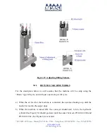
When  the  machine  is  turned  ON,  the  conveyor  should  start  to  run,  the  hydraulic 

cylinder (See Figure 22) should go down until the sensor between PI3100-01-060 and 

PI3100-01-062 (See Figure 4) is activated.  

Summary of Contents for PI-3300

Page 1: ...Telephone 305 8058533 Fax 305 8058535 www acasi com PI 3100 Page 1 OPERATION MANUAL PISTON FILLER MACHINE MODEL PI 3300 CLIENT SIGMA EQUIPMENTS SERIAL 2947 ALL OPERATORS MUST READ AND UNDERSTAND THIS...

Page 2: ...ship or possession of the subject goods or equipment 7 Shipments dates are not guaranteed and are subject to delays due to causes beyond the seller control The seller shall not be liable for late or n...

Page 3: ...7085 NW 46th Street Miami FL 33166 USA Telephone 305 8058533 Fax 305 8058535 www acasi com PI 3300 Page 3 Date Revision Edited Approved Comments 06 2014 I Possin First version...

Page 4: ...main options in the HMI 18 ii Additional settings and other options 21 i Nozzles 21 ii Drip Tray C Guide 22 iii Entry cylinder 23 iv Exit cylinder 24 v Conveyor 25 iii Additional Setting 2 26 VIII PN...

Page 5: ...2 Setting screen centering and drip tray 22 Figure 13 Set the activation time of the centering or the drip tray 23 Figure 14 Main screen of setting the time for the retract operation input 23 Figure 1...

Page 6: ...ctions given in it will help avoid problems that could affect production Following the instructions listed in this manual will also increased the life span of your PI 3300 piston filler Please do not...

Page 7: ...d hose clamps to fasten the tubing to the valves In the machine was purchased with a conveyor installed optional part The conveyor may be sent separately for easier transportation To mount the conveyo...

Page 8: ...L 33166 USA Telephone 305 8058533 Fax 305 8058535 www acasi com PI 3300 Page 8 III PLACEMENT AND INSTALLATION OF THE FILLER MACHINE Decide the machine location according to the dimensions shown in the...

Page 9: ...7085 NW 46th Street Miami FL 33166 USA Telephone 305 8058533 Fax 305 8058535 www acasi com PI 3300 Page 9 Figure 1B...

Page 10: ...7085 NW 46th Street Miami FL 33166 USA Telephone 305 8058533 Fax 305 8058535 www acasi com PI 3300 Page 10 Figure 1C...

Page 11: ...nd ground feeder 60Hz Make sure the Emergency Stop button is depressed at this time d Connect an airline to the quick connect fitting on the filler s regulator right side of control panel Make sure th...

Page 12: ...CLEAN THIS MACHINE WITH BLEACH OR ACIDIC SOLUTIONS These products will react with and attack the sanitary stainless steel components Air filter The air filter must be checked frequently to extract an...

Page 13: ...must also be lubricated after each cleaning or full wash down Conveyor Motor These bearings are sealed and pre lubricated for their life span The motor brushes must be periodically checked to insure...

Page 14: ...8535 www acasi com PI 3300 Page 14 VI GETTING FAMILIAR WITH THE MACHINE i Control Panel All the electrical functions of the machine are controlled through the electric panel a brief description of the...

Page 15: ...ls and processes of the machine are set up ii Electrical system The electrical system controls all the functions of the machine based on the information that is received from the sensors installed thr...

Page 16: ...n through the inputs interprets this information and sends signals through the outputs to execute the various functions and control the filling process Power Supply This component converts 220V AC to...

Page 17: ...filling point These are proximity sensors placed on the adjusting filling bar pieces PI3100 01 060 and PI3100 01 062 see figure 4 they are activated when the pneumatic filling cylinder is extended or...

Page 18: ...ILLER i Setting up the main options in the HMI Follow the steps below to start the set up the conditions of work for your filler 1 Turn the safety lockout switch on the side of the control panel to ON...

Page 19: ...4 Set the number of the speed at which the conveyor works by pressing the blue button in the upper left corner of the main screen see Figure 5 A numeric keypad appears on the screen to enter the numb...

Page 20: ...e button on the right side of the main screen called INSTALLED see figure below A numeric keypad appears on the screen to enter the number Figure 7 Setting number of bottles 6 Set the conveyor ON or O...

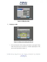
Page 21: ...igure 9 Additional settings i Nozzles 1 In the screen shown in the following figure the times are adjusted before and after filling Figure 10 Screen additional settings Nozzles 2 Selecting any of the...

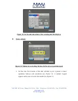
Page 22: ...22 Figure 11 Filling time setting ii Drip Tray C Guide Figure 12 Setting screen centering and drip tray 3 Set the activation time of the centering or the drip tray by pressing the button in the cente...

Page 23: ...time of the centering and the drip tray iii Entry cylinder Figure 14 Main screen of setting the time for the retract operation input 4 Set the time for retraction of the inlet cylinder to give a grea...

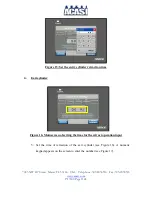
Page 24: ...I 3300 Page 24 Figure 15 Set the entry cylinder retraction time iv Exit cylinder Figure 16 Main screen of setting the time for the retract operation input 5 Set the time of retraction of the exit cyli...

Page 25: ...t the exit cylinder retraction time v Conveyor Figure 18 Main screen setting time to reach the desired speed 6 Adjust the times to reach the desired speed acceleration or deceleration see Figure 18 A...

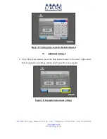
Page 26: ...com PI 3300 Page 26 Figure 19 Setting time to reach the desired speed iii Additional Setting 2 7 For setting more options press the blue button located in the lower right corner this is located in al...

Page 27: ...g the flow controls installed on the machine The flow controls determine the amount of air coming in to or going out of the cylinders when they are activated The standard model machine comes with the...

Page 28: ...ds more accurately Please call Acasi Machinery to obtain specific details regarding this upgrade IX NOZZLES The type and style of nozzles that are optioned on the machine depend on the product s that...

Page 29: ...ese pistons are made of stainless steel class 316L and utilize Teflon seals We offer both standard thread together and sanitary compression fit type pistons To control product flow during the charge a...

Page 30: ...t have the spring area exposed on standard seals filled in with sanitary silicone These seals help avoid product retention between the seal and the spring which will also make cleaning and piston main...

Page 31: ...he emergency cut off valve and manually adjust the center hand wheel PI3100 01 035 See Figure 24 until the nozzles over the two containers are set at the desired position Be sure that the pneumatic cy...

Page 32: ...e height and stroke of the nozzles should be completed a Be sure that the electricity to the machine is turned off and leave the air connected b Open the guide rails and move the entry and exit cylind...

Page 33: ...ere is any kind of container instability consider installing additional guide rails at different heights to combat container movements iii Adjusting the Optical Sensors At The Entry And Exit Of The Ma...

Page 34: ...he fill volume turn the hand wheel PI3100 01 059 which raises or lowers the proximity sensor Once the proximity sensor is set in the desired position it will detect the platen on the end of the piston...

Page 35: ...he pistons open or close the flow control valve See Figure 22 d To change the charge speed of the pistons open or close the appropriate flow control valve See Figure 22 Note Consider that when changin...

Page 36: ...he machine will be setup using the Down type fill cycle and with just one stroke per fill cycle a When the air feed for the machine is connected the nozzles should go up until the nozzle bar reaches t...

Page 37: ...nder rod should extend and the conveyor should stop f When the nozzles reach the bottom of the stroke the fill cycle should start g When the fill cycle has ended the nozzles should go up and pistons s...

Reviews: