background image

Summary of Contents for RC-96

Page 1: ... RC 96 Repeater Controller Owner s Manual Advanced Computer Controls Inc ...

Page 2: ......

Page 3: ...to comply with the limits for a Class A computing device pursuant to Subpart J of Part 15 of FCC Rules which are designed to provide reasonable protection against such interference when operated in a commercial envi ronment Operation of this equipment in a residential area is likely to cause interference in which case the user at his own expense will be required to correct the interference Specifi...

Page 4: ......

Page 5: ...etin boards etc using the message editor The scheduler works in conjunction with the time of day clock and your existing macro sets It relieves you of the chore of repetitively manually selecting different macro sets at different times of the day and days of the week It s like an automatic control operator With programming commands you select the time and days every day weekends only etc for autom...

Page 6: ...n at no charge except return shipping If you would like us to perform the upgrade return your controller and the upgrade kit to ACC before attempting installation If you choose to perform the installation in the field please recognize the small but finite risk WARNING Version 5 firmware requires 8Kx8 of E2PROM All RC 96 controllers are equipped with the necessary 8Kx8 Very old RC 85 controllers sh...

Page 7: ...t the chips are plugged into their sockets in the proper orientation and with no bent pins 7 Power up the controller it should sign on with the V5 x message Proceed to program the new functions of the controller as described in the next sections RC 85 Repeater Controller CAUTION You must either have an 8Kx8 E2PROM at location U27 or have obtained an 8Kx8 E2PROM from ACC before performing the insta...

Page 8: ...oller has a Tone Panel option enable tone encode if programmed as encode and desired on 81 Programming Programming commands shown Program your Control Op setup in macro sets so that what you ve selected above isn t undone when you select a new macro set 5911 5915 Program Link COS to be high true previous fixed condition 541l If you have an FC 900 Interface connected to your controller indicate whi...

Page 9: ...he same format Set Time 12 hr mode 4100 AP HI0 HI MIO Ml Set Time 24 hr mode 4100 HID HI M10 M1 AP 1 p m 0 a m 12 hour mode only HlO tens hours H1 ones hours MID tens minutes Ml ones minutes Example It s 2 53 05 p m To set the clock using 12 hour mode wait until nearly 2 54 and enter the command with the controller unlocked 4100 1 0254 and unkey Time your command entry so that you unkey at 2 54 00...

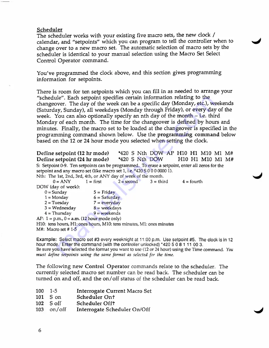
Page 10: ...ck Define setpoint 12 hr mode 420 5 Nth DOW AP H10 H1 M10 M1 M Define setpoint 24 hr mode 420 5 Nth DOW H10 H1 M10 M1 M S Setpoint 0 9 Ten setpoints can be programmed To erase a setpoint enter all zeros for the setpoint and any macro set like macro set 1 i e 420 S 0 0000001 Nth The 1st 2nd 3rd 4th or ANY day of week of the month o ANY 1 first 2 second 3 third 4 fourth DOW day of week 0 Sunday 5 Fr...

Page 11: ... fifteen four 804 sixteen five 805 seventeen six 806 eighteen seven 807 nineteen eight 808 twenty nine 809 thirty ten 810 forty eleven 811 fifty Male crane 950 gauge device 953 micro electrician 943 mill farad 930 passed Sound Effects crowd 892 tic explosion 891 toc laser 873 train phaser 882 whistle Run Time Variables 812 good 834 813 morning 841 814 afternoon 842 854 evening 843 864 the 821 874 ...

Page 12: ...equency mode and memories can be selected The user commands for these functions are Receive Only HF Prefix 1 Receive Transmit HF Prefix 2 Off HF Prefix 3 Frequency Interrogate HF Prefix 8 Frequency Enter HF Prefix lOM M HT O h t Examples assuming HF Prefix factory default value of 1 14 23 MHz 1 14 23 3 89551 MHz 1 3 89551 7 255 MHz 1 7 255 21 3 MHz 1 21 30 Bump Up 100 Hz HF Prefix 6 Bump Down 100 ...

Page 13: ...ches reverse patches and patches made by the mobile in all four regenerate modes Example We have four decode tones installed in positions 2 5 Encoder at position 1 should regenerate the incoming tone only while the mobile is present and the controller should not respond to other incoming tones until the repeater carrier is allowed to drop Enter the command with the controller unlocked 5101 41 Auto...

Page 14: ...as indicated in the instructions supplied with it to generate the Serial Out signal 85 96 TS 440S Tx Audio Tx Audio AFSK IN J4 8 CLINK 6 green Link Rx Audio Link Rx Audio AFSK OUT or speaker jack J4 6 LINK 7 blue PTTL PTT ACC2 jack pin 13 or REMOTE LINK 4 orange From standby switch CX3 Serial Out Serial Input ACCI jack pin 3 J3 11 CNTL RX 6 green bottom pin For the RC 85 controller DIP Switch 4 mu...

Page 15: ...roller won t hang up Band units not present in your Ie 900 stack can be locked out from selection to avoid potential confusion See Appendix C Programming Commands When using the FC 900 Link 2 can be disabled if you have only one band unit to avoid confusion See Appendix B Control Operator Commands Bands can be swapped without Link 2 unit needing to be on A band unit cannot be selected for both Lin...

Page 16: ...12 ...

Page 17: ...lephone Line 12 FCC Notice to User 12 Setting DIP Switch Options 13 Setting Audio Levels 13 3 Command Code Structure 15 Introduction 15 User Commands 16 Control Operator Commands 16 Programming Commands 17 Command Evaluation 17 Special Keys 18 Command Decoder Timers 19 4 How to Command the User s Features 21 Introduction 21 Touch Tone Pad Test 21 Autopatch and Autodial 22 Activating the Autopatch ...

Page 18: ......

Page 19: ...ating the User LoadableAutodialer 29 Activating the Emergency Autodialer 30 Reverse Patch 31 the Phone 31 Answering the Reverse Patch Over the Air 32 Extending the Telephone Timer 32 Information 33 Rea ding Reading Back Your Signal Strength 33 Bulletin Board 33 Linking and Paging 34 Crystal and BCD Controlled Radios 34 FC 900 Interface 35 Unmuting Touch Tone 37 Call Decoders 37 Two Tone Paging 38 ...

Page 20: ... J _ ...

Page 21: ...troller 51 Introduction 51 Unlocking and Locking 51 Programming the Unlock Code 52 Messages 52 Tone Parameters 56 Courtesy Tone Selection 57 Timers 57 Command Code PrefIxes 58 Emergency Autodial Numbers 59 Miscellaneous Selections 59 Store Macro Sets 60 Pager Memories 60 Tone Panel Frequencies 62 7 General Operation 63 Introduction 63 Command Channels 63 Control Over the Telephone Line 64 Access 6...

Page 22: ......

Page 23: ... External Tape Player 81 Digital Voice Recorder 82 Sharing the Phone Line 83 9 How It Works 85 lOIn Case of Difficulty 89 Maintenance 89 Servicing 89 General Checklist 90 Trouble shooting Chart 90 Most Often Asked Questions and Answers 91 A User Command Code Summary 95 B Control Operator Command Summary 99 C Programming Command Summary 103 D Programming Sheets 117 Factory Presets 117 Custom Config...

Page 24: ......

Page 25: ...4 Table F 2 DIP Switch Descriptions 135 Table F 3 DIN Connector Pinouts 136 Table F 4 Interface Connector Cross reference 136 Table F 5 Connector Pin Functional Descriptions 137 G Schematic 139 H AD 2 Audio Delay Board Kit Option 143 Description 143 Installation 144 Adjustments 144 Schematic 146 I CTCSS Tone Panel Option 147 Introduction 147 Installation 147 Programming 148 Control Operator Select...

Page 26: ......

Page 27: ......

Page 28: ......

Page 29: ... controller s non volatile memory But that s just part of the story your repeater can talk to you The IDs can be in natural sounding synthesized speech so your users don t have to be CW buffs to understand what the repeater is saying Add to that the RC 96 controller s custom repeater oriented speech vocabulary of nearly 500 words and you can easily construct informative ID messages for your repeat...

Page 30: ...e Two tone five tone and DTMF paging offer selec tive calling through your repeater to standard pocket pagers which means users don t have to be listening to be available Remote programming is the key to the flexibility and power of the RC 96 controller Its Touch Tone command set allows remote reprogramming of messages autodial numbers command codes and more The remotely programmed information is ...

Page 31: ...ge caused by lightning Remotely programmable with Touch Tone commands Messages 25 ID s tails Bulletin Boards phone answer etc Morse code parameters Speed 12 30 WPM Pitch dc 3000Hz Control Op and user command codes 20 prefix groups up to 7 digits each Courtesy tone selection from 10 predefined sets Timers 16 sets 0 30 minute with 1 second resolution Autodialer numbers 200 Pager memories 1000 Non vo...

Page 32: ...th programmable timeout Control of repeater from telephone Remote control logic outputs 3 expandable to 8 Low distortion computer synthesized tone generation Courtesy Tones 10 selectable sets Noise and kerchunker filtering Touch Tone muting Control receiver provisions Site alarm logic input Intelligent ID algorithm automatically selects from up to 7 programmable ID s Tail messages 3 programmable r...

Page 33: ...ck Board Kit tofully mute Touch Tone and squelch tails through the repeater FC Frequency Control Board for frequency control of BCD remote base transceivers and remote control output ex pansion FC 900 Interface for frequency control of the rCOM rC 9xx FM Mobile band units as remote bases or links and remote control output expansion RC 96 REPEATER CONTROLLER OWNER S MANUAL 5 ...

Page 34: ...Chapter One Introduction and Specifications 6 RC 96 REPEATER CONTROLLER OWNER S MANUAL ...

Page 35: ...goes to the transmitter it needs to connect directly to the transmitter s audio input Figure 2 1 RC 96 Front Panel Since all the control functions are handled internally by the RC 96 controller the only connections absolutely necessary to the rest of the system are these four basic signals plus power Figure 2 2 Connecting a phone line to the controller lets you use the patch reverse patch telephon...

Page 36: ...supply and an optional backup battery are provided at the POWER connector and at the terminal block 12V an GND terminals The primary supply and optional battery can connect to either power input The power inputs are diode isolated so that the battery is normally isolated from the load through a back biased diode until the primary supply goes away at which time the battery instantly begins supplyin...

Page 37: ...put from the receiver which indicates that a signal is present is called COS or carrier operated switch It s a logic signal which is at a particular logic state when an RF signal is at the receiver s input or the squelch is open and at the opposite state when there is no RF signal and the squelch is closed Most receivers designed for repeater service have such a logic output called COS COR squelch...

Page 38: ...g logic High or low true operation is selected by a DIP switch option For a high true PTT set DIP switch 2 ON for low true PTT set it OFF If your transmitter has negative voltage on the keying line it s necessary to buffer PTT with a relay or transistor circuitry The PIT transistor switch is capable of keying positive voltages only and can be damaged if connected to a negative voltage 60 y oft v 1...

Page 39: ...1 present eo mV 1Vp p If JP1 absentI 0 5 V 5 V p p Transmitter Audio Figure 2 5 Receiver Audio Input REPEATER Connector Pin 7 blue Audio is supplied by the controller to the transmitter Any existing internal audio paths in the repeater should be disabled Transmitter audio consists of receiver speech synthesizer tone link and phone patch audio switched and mixed under the control of the computer in...

Page 40: ...e provided by the telco RJIIC See equipment FCC Compliance label 2 This device may not be used on telco operated coin phone lines Party lines and privately owned coin phones are subject to local State regulatory policies and possible additional State special requirements 3 The telco has the right to make changes to their network which can affect the operation of your equipment provided you are giv...

Page 41: ...EPEATER TX PTT HIGH TRUE LOW TRUE SW3 tWm tmtlfl 1 1111 lwrttfrmrml 1 ON OFF Figure 2 7 Initial DIP Switch Settings Several of the audio levels to the transmitter and phone can be adjusted with a small screwdriver using pots accessible from the rear panel Although they are preset at the factory the levels of the speech synthesizer and tone generator can be adjusted with p c board mounted pots acce...

Page 42: ... limiter The audio level from the phone PHONE should be adjusted during a phone patch The audio drive level into the telephone can be adjusted with the pot labeled PH DRV on the rear panel and would typically be set to maximum If the patch will be operated full duplex the hybrid balance pot R108 on the board can be adjusted during a patch for the best null This completes the basic installation of ...

Page 43: ...r activating the autopatch remote base bulletin board and other user type functions The user command level is the lowest level ofcommand classification Control Operator commands are those which allow enabling and disabling the various functions of the repeater and selection of various operating modes For example the Control Op can select between carrier and CTCSS access or enable and disable the a...

Page 44: ...next chapter of the manual Control Operator commands which enable and disable various repeater functions and select operational modes consist of a command prefix which can be programmed by the repeater owner remotely with Programming commands followed by a one or two digit root code The command prefix can consist of between 1 and 7 digits so that Control Op commands can be made as secure as is nec...

Page 45: ... how to change it After you ve finished a session of programming you lock up the controller sothat it s secure from tampering If you forget to lock it the controller will lock itself after one minute of no commands The classes ofProgramming commands are found in Chapter 6 The controller evaluates Touch Tone commands to determine the function requested COinrnands can be entered 1 from the front pan...

Page 46: ... input and the Control Op wants to disable the repeater timer and the Repeater Timer Disable command is 12303 he can enter 12303D and the com mand will be accepted by the controller even though the carrier has not dropped When sending a command to the controller over the air if you make a mistake part way through the sequence a key will cancel the digits sent to that point during the transmission ...

Page 47: ...help the controller discriminate between valid command sequences and the rare occasional false decode on voice These timers impose two simple but imponant requirements on command entry 1 Command sequences can not be enteredv e r y s l o w I y because if more than four seconds elapses between digits the controller will disqualify the command 2 Command sequences can not be entered at the beginning o...

Page 48: ...Chapter Three Command Code Structure 20 RC 96 REPEATER CONTROLLER OWNER S MANUAL ...

Page 49: ...these overall groups Touch Tone Pad Test Autopatch and Autodial Reverse Patch Reading Information Linking and Paging Other Activities Since your Touch Tone pad is used for entry of all commands to the controller it may be a good idea to check it out The controller allows you to easily and thoroughly test your pad by letting you enter a sequence ofkeys and it reads the sequence back to you in voice...

Page 50: ...l as one command Try preflX 7273330 The controller will say Autopatch pause then read back the phone number for verification and pause again During either pause if you want the controller to dial the number click your rig s PTT briefly By clicking your mike at the first pause you prevent phone number readback Waiting until the second pause lets you verify that the proper number was entered You can...

Page 51: ...atch User Autodial or Emergency Autodial Timertimes out the 30 seconds left message is gener ated The user can then enter the Patch Timer Extend command If the Activity Timer times out a warning warble is generated reset the activity timer by sending a brief transmission The Activity Timer will time out if a user makes too long a transmission Phone Hangup Message Patch Dialing Prefix Autopatch Tim...

Page 52: ...ing The controller says Repeat dial and dials the number In case of malicious patch hangup during a call you can define your own three digit hangup code prior to making your call again The Custom Hangup Code permits you to define the hangup code which inhibits the Patch Hangup command from hanging up the patch To define a custom hangup code enter the command within 15 seconds of initiating the pat...

Page 53: ...ways on to be user selectable or to be disabled To activate the cover tone if in the user selectable mode enter the Cover Tone Command before or during a patch The cover tone selection is cancelled at the end of the patch and can be selected again for the next patch Patch Utility PreflX 2 Patch Utility Prefix and User Selectable User enters 2 before or during a patch Controller responds with C and...

Page 54: ...and operate the patch half duplex The activity timer is disabled during full duplex patches Patch Utility Prefix l Patch Utility prefix Full Duplex User Selectable User enters 1 before or during a patch Controller says 0 and prepares for full duplex patch Patch Utility prefix Full Duplex Always On User wants this patch only to be half duplex User enters I before or during the patch Controller says...

Page 55: ...y to keep up with new users and users that move or want to add or delete numbers There are two banks of User Loadable Autodialer numbers the fIrst bank Bank 0 holds locations 10 99 and the second bank Bank 1 contains 100 199 although addresses in the second bank are specified by their last two digits only Each bank has its own load erase command code prefix The phone number can be secured from rea...

Page 56: ...odial Bank 1 Load Erase Prefix 457 User sends 457 207273330 Controller says Autodial Write and loads location 120 with the phone number 727 3330 Activating User Loadable Autodialer does not allow phone number readback If you don t want users to be able to erase and change autodial numbers either keep the autodialer locked with the Control Op command or keep the LIE command code prefix secret If an...

Page 57: ...one number readback of an autodial slot by having se lected the security option when loading the number into the User Loadable Autodialer The Control Operator can bypass the security mode to allow verification of the numbers stored if necessary with the Unhide command Ifyou ve made a mistake entering the autodial command you can cancel the request by entering any Touch Tone during either pause or ...

Page 58: ...bers but are programmable messages like Op erator Fire Police etc These ten numbers areintended for emergency public service agencies and the response indicates selection of the correct agency The Emergency Autodialer does not require that the user click his mike to initiate telephone dialing The patch is terminated just like the Autopatch and User Loadable Autodialer Emergency Autodial Prefix Loc...

Page 59: ...s mode allows callers without Touch Tone phones to use the reverse patch while still allowing commands to be entered over the telephone Mode 2 causes the controller to ring out when the Phone An swer Delay Timer time outs but the line is not answered until a repeater user enters the Reverse Patch Answer command over the air Mode 3 is similar to Mode 0 except that it is optimized for talkback pagin...

Page 60: ...e Patch Utility Command Prefix Mter entermg the com mand the user must unkey in order to let the controller evaluate the command and connect the caller to the repeater patch Utility Prefix Patch Utility Prefix User sends while reverse patch is ringing Controller connects caller to the radio After entering the command unkey and listen for Morse code 1 beep beep to be sure the patch is connected Whe...

Page 61: ...red reading is spoken in synthesized speech The meteriscalibrated in S units and dB from SO to S9 plus 60 S Meter Command S Meter Command 8 User s signal strength into the repeater is S9 20 User keys down at least one half second and sends 8 Controller says S9 plus twenty Be sure to key down at least 1 2 second when entering the com mand S Meter Command Code User Command EnablelDisable Users can c...

Page 62: ...e link or remote in listen only mode Signals received over the link transceiver bring up the repeater transmitter and are retransmitted over the repeater Users can talk on the repeater however without interfering with the stations on the link frequency Repeater users audio overrides link audio to allow a conversa tion to take place in this mode The user can activate the link transmitter Now repeat...

Page 63: ...ink 2 Band Select x B mI RxFRange IxQrfgts IxFRange J X 0 1240 1240 000 1249 995 MHz S 12MHz 1240 000 1261 995MHz 129A 10m 29 000 29 695 MHz S lookHz 29 000 29 695 MHz 19A 2 2m 144 000 147 995MHz S 6OOkHz 144 ooo 147 995MHz 29A H 3 220 220 000 224 995 MHz S I 6MHz 220 000 224 995MHz 39A 4 440 440 000 449 995MHz S 5MHz 438 000 449 995MHz 49A 5 430 430 000 439 995MHz S 5MHz 425 000 444 995MHz 49A 6 ...

Page 64: ...ncy Link 2 Frequency The band segments assigned to Link I and 2 can be swapped This pennits quick access to transmit which is permitted only from Link 1 Link PreflX Swap Link 1 Link 2 Bands The band units include provisions for high low power selectiQn Band Unit Power Level 10M 6M 1200 MHz 10 or 1 Watt 2M 220 440 MHz 25 or 5 Watts 2M UX 29H 45 or 5 Watts Commands are available for selecting high o...

Page 65: ... MCl code and phone number to pass unmuted while ignoring the sequence Be sure to send the at the beginning of each transmission that you want unmuted Ifyou would like all Touch Tones to be unmuted and would like the controller to decode the commands use the Control Op selectable Touch Tone Unmute mode The controller can generate various paging tones in response to Touch Tone commands entered from...

Page 66: ...kward compatibility to the RC 85 controller and for additional flexibility in two tone paging an additional paging command is available which allows the user to directly specify the tones to be generated One second I three second two tone and eight second group call tones can be generated The paging command consists of the paging preflX followed by the group number and tone number of each of the t...

Page 67: ...of an exchange of transmissions When taken up the Touch Tone Access Mode Timer will take the repeater back down after a period of inactivity Ifin the Control Op selected PL Access Mode Touch Tone Access Up allows carrier access to the repeater Touch Tone Access Down restores the need for crcss to access the repeater When controller is in CTCSS with Touch Tone Access Enabled Touch Tone Access Up al...

Page 68: ...n response to the command entry the controller provides a high or low beep tone to indicate the current state of the output Certain of the UP outputs take on dedicated functions when various options are selected For example UF 3 becomes a Phone Line Busy output when in the Phone Line Shared mode UP commands to dedicated outputs are ignored by the controller UP Prefix Output 1 8 1 on low 0 off high...

Page 69: ...nds can total two to nine digits The entire command is entered as one sequence i e prefix root as one transmission over the air or prefix root from a phone or the front panel The controller responds to each Control Op command with a unique response message so that the Control Op knows for sure that he entered the correct command TheJonnat used for command description is as follows root code respon...

Page 70: ...ry out many routine Control Op chores Repeater Enable A pair of commands allow the Control Op to enable or disable Disable Commands the repeater s transmitter The Repeater Enable command also enables the Site Alarm 00 RE Repeater Enablet Enables repeater transmitter 01 RD Repeater Disablet Disables repeater transmitter Example Control Op Prefix 123 Enter 12301 to disable the repeater Hints These c...

Page 71: ...n external crcss decoder indicating to the controller that subaudible tone is present ona signal at the receiver or the optional internal Tone Panel board The Carrier Access Control mode allows full access and control without the need for crCSS The crcss Control Op Command mode allows carrier access to the repeater and carrier access to User commands but re quires crcss for activation of Control O...

Page 72: ...optional Tone Panel 91 98 ID 8D Tone Panel Tone Disablet Disables tones 1 through 8 on the optional Tone Panel CA PC PU and PL are mutually exclusive ME and MD are mutually exclusive but Touch Tone Access can be enabled ME along with CA PC PU pL condition When in crcss Access Touch Tone Access overrides the need for crcss for access and is an alternative to the need forCTCSS The Control Op can ena...

Page 73: ...led phone numbers with a leading zero or one or longer than seven digits are not permitted by the Autopatch The User Loadable Autodialer can be locked which prevents erasing or loading phone numbers The patch timer which includes the overall timer and the activity timer can be enabled or disabled Separate overall timer values are permitted for the Autopatch and each Autodialer and for the activity...

Page 74: ...command can be used over the air to hang up the patch in case a user has defined a custom hangup code and forgotten the code he defmed 19 PE Autopatch Enablet Enables Autopatch 20 PD Autopatch Disablet Disables Autopatch 27 LE Long Distance Enablet Enables Autopatch long distance 28 LD Long Distance Disablet Disables Autopatch long distance 21 UE User Autodial Enablet Enables User Loadable Autodia...

Page 75: ...fThook Manually takes phone offhook 44 Control Op Onhook Places phone onhook hangup Hints When controlling from the phone hang up with Control Op Onhook Ifsomeone forgets his custom hangup code hang up with Con trol Op Onhook Emergency Autodial never requires user to click his mike to initiate dialing Ne XC and NR are mutually exclusive Disabling all patch timers can be dangerous These commands al...

Page 76: ...These commands are mutually exclusive only one is in effect at a time The Control Op can select from three remotely programmable tail messages to be generated occasionally just before the re peater carrier is allowed to drop He can also disable the tail message function Tail messages are useful as reminders of events to users or to indicate repeater status or emergency conditions 35 Tl Tail Messag...

Page 77: ...is generated in place of the other ID messages Other command responses may not completely convert from speech to Morse so operation in Speech Disable mode should be limited to special circumstances The Kerchunker filter can be enabled or disabled 61 KE Kerchunker Filter Enablet Enables kerchunker filter 62 KD Kerchunker Filter Disablet Disables kerchunker filter The Control Op can cause Touch Tone...

Page 78: ...CT Courtesy Tone Low Selectt Selects Bumblebee 72 CT Courtesy Tone Low Selectt Selects Yellow Jacket 73 CT Courtesy Tone Low Selectt Selects Shooting Star 74 CT Courtesy Tone Low Selectt Selects Comet 75 CT Courtesy Tone Low Selectt Selects Stardust 76 CT Courtesy Tone Low Selectt Selects Duncecap 77 CT Courtesy Tone Low Selectt Selects Piano Chord 78 CT Courtesy Tone Low Selectt Selects Boop 79 C...

Page 79: ... not accessible Programming commands are accessed by temporarily unlocking the controller with a custom unlock command unique to the controller that provides security against tampering When the controller is unlocked only Programming commands are recognized The unlock code is programmed or changed if necessary at the site by the repeater owner with the controller locked While the controller is unl...

Page 80: ... messages Emer gency Autodial responses telephone answer and hangup mes sages alarm message and two Bulletin Board messages Messages can only be entered or changed while the controller is unlocked The message to be edited is selected with the appro priate Touch Tone Programming command Then the message is entered based on Morse code character shown below or speech vocabulary Touch Tone representat...

Page 81: ...eypadLayout Morse code character codes aret epeated and speech synthesizer vocabulary codes are shown in Appendix C and on the Message Editing Reference Card A pause in voice messages can be generated using the code 34 Several Message Editor commands control its operation 0 When you ve completed editing the message and it s correct it can be stored in the controller s nonvolatile memory by enter i...

Page 82: ...return to the UL prompt ready to accept additional Programming commands or to lock up the controller To illustrate here are two editing examples a Morse code ID for the Forced CW ID Message and a speech Bulletin Board message First if the controller is not already unlocked enter the unlock command Then select the message to be edited with the command 1001 1001 over the phone The controllerre spond...

Page 83: ...ricks were used code 915 s suffix after tonight codes 30 and 60 to build up thir ty code 34 for the pause between sentences the use of codes 23 and 82 C and U to get See you and finally codes 956 and 210 to make late r Message Commands Command Messaee Name Response Max of Morse SPeecb Characters 1000 1100 Initial ID IT 20 1001 Forced CW ID FI 12 1002 1102 Anxious ID AI 12 1003 1103 Pending ID 1 PI...

Page 84: ...ess the external tape player enter the command 1324 and load the character X 92 then write the message into memory See Chapter 8 for details of inter facing the external tape player Digital Voice Recorder tracks can be addressed from any programmable message For example To load OVR track 20 into Pending ID 1 enter 1303 The controller responds with Pl Using the vocabulary codes enter P20 with 71020...

Page 85: ...et 9 Beep 3001 ct CT SEL Logic High Tone ct 0 9 cr 3002 ct Link Tone ct 0 9 CT Hint If the no tone set is selected users must still wait about 650 ms between transmissions to allow the timeout timer to reset Timers Several of the repeater s timers can be modified including the hang timer timeout timers patch related timers and tail message timer The timer value is entered directly in seconds milli...

Page 86: ...ode prefixes for Control Operator commands and the various classes of User commands can be changed remotely Prefixes The desired prefIX is entered directly as part of the Command Code Prefix Pro ng commands Each prefix can be 1 to 7 digits long An empty prefIX can be loaded for functions that are not used SOOO prefix Control Operator Command CMD SOOI prefix User Function Logic Output CMD S002 pref...

Page 87: ... dial pulse rotary signalling into the phone can be selected for patch operation Control Operator and Programming control can be permitted or not permitted through the repeater receiver can be prohibited for overall security The controller can be set up for shared or unshared use of the phone line see Chapter 8 Shar ing the Phone Line Finally the logic sense of the User Function remote control log...

Page 88: ... MACRO 5912 Store Macro Set 2 MACRO 5913 Store Macro Set 3 MACRO 5914 Store Macro Set 4 MACRO 5915 Store Macro Set 5 MACRO The fonnat and address of one thousand pagers can be stored in the controller s memory Several fonns of two tone sequential 5 6 tone sequential and DTMF are supported 29 xxx f aaaa aa PAGE xxx three digit memory number 000 999 f pager fonnat o 1 second 3 second two tone 1 2 7 ...

Page 89: ... 161 100609 147 47005 1 810 2 197 1i57 6 8 119 510 5 128 819 0 III 1014 7 149 496 8 158 855 5 198 1395 0 9 119 539 0 129 928 1 162 1063 2 149 524 6 159 903 2 199 1433 4 0 110 JJO 5 120 569 1 1S9 1092 4 140 321 7 150 553 9 190 1122 5 8E TYPE 99TONE FREQUENCIES TOilE GROUP 7 ROUP 8 ROUP iii fREQ fRm a fREQ C o 600 1 592 5 607 5 712 5 1 741 2 882 2 757 5 787 5 772 5 a 1023 5 802 5 852 5 817 5 4 1164 ...

Page 90: ...Tone T Frequency Tone x 1 8 FF from table below Note The controller must be Reset for Tone Panel commands to take effect Enter COP prefix 18 after locking the controller CTCSS FREQUENCIES 01 67 0 11 21 136 5 31 192 8 02 71 9 12 100 0 22 141 3 32 203 5 03 74 4 13 103 5 23 146 2 33 210 7 04 77 0 14 107 2 24 151 4 34 218 1 05 79 7 15 110 9 25 156 7 35 225 7 06 82 5 16 114 8 26 162 2 36 233 6 07 85 4 ...

Page 91: ... AUDIO BAT 1 1 PHONE BATTERY RC 96 PHONE LINE iGND Fig 7 1 Repeater BlockDiagram The controller s command decoder and command structure were described in detail in Chapter 3 We ll describe here the com mandchannels along with access modes lO courtesy tone tail messages and other aspects of the controller s operation Commands can be entered from the front panel keypad over the repeater receiver the...

Page 92: ...e A User level Telephone Timer Extend command is available for reloading the timer for Digital Voice Recorder related activities and is useful when loading or chang ing autodial numbers The controller can also be unlocked to allow Programming commands to be entered User commands can be entered over the phone including the Reverse Patch command code to activate the Reverse Patch This code causes th...

Page 93: ...cess to the repeater and its command structure over the repeater receiver The optional ui1t incresS tone panel encoder decoder or an external cress logic signal in conjunction with Control Op commands allows 1 Carrier access and carrier control 2 Carrier access and User command control but crcss required for Control Operator and Programming control 3 Carrier access but crcss required for User Com ...

Page 94: ...or no repeater activity or for users to let the repeater carrier drop Ifthey do the controller sends a Pending ID Mes sage at the end of the repeater hang time The Pending ID can rotate between three ID messages for variety In addition a Special ID Message can be added to the rotation for special events The Pending and Special IDs can conveniently contain informational messages as they occur witho...

Page 95: ...o tone can be chosen for use on the repeater with Control Op commands A CourtesyTone Select logic input to the controller chooses be tween the Control Op selected set and a second set selected by a progranu ping command allowing the courtesy tone to convey in fonnation high low power emergency power etc A third selectable tone set indicates a signal received on the link or remote base receiver dif...

Page 96: ...g the ID message will be generated in place of the courtesy tone and will be followed by the tone In either case the timeout timer resets at the beginning of the courtesy tone orAnxious ID If users don t wait for the courtesy tone and the total transmis sion time between timer resets exceeds the programmable time out timer value the controller will announce Repeater Time Out and the transmitter wi...

Page 97: ...peater ofto the telephone line if necessary The Control Op can disabkTouch Tone muting so that all tones pass through the repeater TheRC 96 controller provides filtering against noise and ker chunking on the repeater receiver An algorithm fIlters against spurious noise on the receiver COS logic input preventing static crashes and random noise bursts from bringing up the repeater Kerchunker filteri...

Page 98: ...Chapter Seven General Operation 70 RC 96 REPEATER CONTROLLER OWNER S MANUAL ...

Page 99: ... to the crCSSLogic Input on the Repeater connector pin 5 A logic low must be less than 8 volts and a logic high greater than 2 4 volts Ifthe decoder s output is open collector tie a pullup resistor approximately 10K from the output to the 12 volt sup ply A popular tone decoder is the Communications Specialists TS 32P The diagram below shows how the TS 32 may interface with the repeater receiver an...

Page 100: ... T8 32 arr l I 2 Fig 8 1 Communications Specialists TS 32 Subaudible Tone Decoder Interface Talking S Meter REPEATER connector pin 3 The controller is capable of measuring a 0 5 volt S meter signal and reading back the measurement to the user in synthesized speech on command The signal should be conditioned if neces sary to range from zero volts SO to approximately four volts S9 plus 60 and should...

Page 101: ...er audio may connect to the Control Receiver connector pin 7 and should be in the range of 5 to 2 5 volts peak to peak The COS signal should connect to the Control Receiver connec tor pin 1 The COS may be high true or low true DIP switch 3 should be set based on its logic sense ON for high true OFF for low true IT a control receiver is not connected DIP switch 3 must be ON For greater security a c...

Page 102: ...rity in intrusion detection applications a pull up resistor on the board can be grounded by a normally closed switch and iithe switch is opened or if wires are cut the alarm will be activated Activation of the site alarm causes the alarm message to be announced over the repeater transmitter at 15 second intervals until cleared by a Control Op or until the Alarm Timer times out The alarm condition ...

Page 103: ... site to indicate that another controller is currently using the phone line See Sharing the Phone Line later in this chapter An external cartridge tape player may be interfaced to the con troller to play ID tail or Bulletin Board messages The activa tion of these messages when loaded properly with the Message Editor can cause a one second pulse to be generated at Control Output 2 UF 2 to start the...

Page 104: ...ol Output Mode Selections S RI L CLOCK SERI L 101 1 01_141_161 1_1 1 Ollnlul _ 11111111111111111111 n OAT SERI L U TRANSffR L SERI L OAT TO R Hl JTE IlASE 0 DCPANDED UF J L SERI L OAT TO O fR J Fig_8 7 Serial Timing and Data Bit Definitions 0 UFI 8 MHz DO 16 1O s KHz DO 1 UF2 9 MHz 01 17 10 s KHz 01 2 UF3 10 MHz 02 18 10 s KHz 02 3 UF4 11 MHz 03 19 1O s KHz 03 4 UF5 12 PLUS MINUS 20 100 s KHz DO 5...

Page 105: ...he frequency verifies command entry A fixed frequency link or remote base transceiver may be con trolled by the RC 96 controller by connecting link PTT link COS link receiver audio and by driving the link transmitter with repeater transmitter audio External shift register ICs capture the data shifted out of the controller and at the same time may perform any level translation required in interfaci...

Page 106: ...he ICOM IC 9OOA Super Multi Bander System band units for an easy to hook up remote base or link installation The FC 900 provides the electronic interface to the ICOM internal bus transmit audio processing including pre emphasis symmetrical limiter and level and deviation controls receive audio process ing including squelch pots for each band unit de emphasis and squelch gating programmable crcss e...

Page 107: ...eeded ACC FC 900 BAND UNIT BAND UNIT BAND UNIT BAND UNIT BAND UNIT BAND UNIT front vi ew Fig 8 12 FC 900 Interface Mechanical Hookup The ICOM band units operate from 12 volts which must be supplied from a power supply capable of supplying high current on a continuous basis In addition the FC 900 requires 12 volts at 25 mAo The band units are intended to plug into ICOM s Interface Unit B which you ...

Page 108: ... learn how to command the trans ceivers The adjustments are straightforward to make after the units are turned on Squelch Pots Pots RI04 RI09 are adjusted for the desired squelch setting when the respective band unit is selected Bring up the band unit in receive only and adjust the respective pot each pot is labeled on the board by band Transmit Level RI03 adjusts the level of the transmit audio a...

Page 109: ...6 6 UP3 3 UF7 7 UP4 4 GND 8 and shield LINK connector pins 1 and 7 User commands may allow selection of a weather radio scanner or other audio source The audio input shares the Link Remote Base receiver input and is available if the link function is not used The audio is gated to the transmitter under computer controlin response to the user commands and the transmitter P1T is held active The audio...

Page 110: ...96 controller so that any of the remotely recordable tracks may be addressed through the Message Editor Control signals are passed to the DVR through Control Output 1 Serial Data DVR connector pin 4 as part of the serial data stream supplied at that output in the expanded remote control output mode Information from the DVR is supplied to the RC 96 controller through the External Device Busy logic ...

Page 111: ...ing command User Function 3 becomes a low true phone line busy output which may be or tied with other controller s busy outputs The signals are also connected to all the controllers Phone Line Busy inputs When a user attempts to bring up the patch and the phone line is in use by another controller the RC 96 controller responds by saying Busy If the phone line is not in use the patch proceeds and t...

Page 112: ...Chapter Eight Interfacing to Other Equipment 84 RC 96 REPEATER CONTROLLER OWNER S MANUAL ...

Page 113: ...r functional blocks include the microcomputer audio switching and mixing circuits buffered I O speech synthesizer tone generator Touch Tone decoder and telephone interface In addition various protective circuits ensure reliable long tenn operation with automatic error recovery The microcomputer consists of an 8085 microprocessor U25 with 80K bytes or more ofEPROMprogrammemory U29 U34 8K of E2PROM ...

Page 114: ...bility The speech synthesizer U23 mterfaces to the CPU through I O ports and is controlled by the microcomputer program The pot RI09 adjustment sets the synthesizer clock frequency setting the pitch of the voice The tone generator U26 creates Morse code courtesy tone and Touch Tone audio under control of the computer program The Touch Tone receiver U14 may connect to any of the audio input channel...

Page 115: ...w It Works YATCH DOG CPU no 12 BAT RCYR 1 10 TOf SPEECH LNC TEI PIfJNE r _ 12 PO w ER L _ of5 SUPPLY 9 I 5 I 011 TO 1 1 SOIJaS LOGIC CM1 R 110 RC t R 1 11 110 TIP LNC RING Fig 9 1 System Diagram RC 96 REPEATER CONTROLLER OWNER S MANUAL 87 ...

Page 116: ...Chapter Nine How It Works 88 RC 96 REPEATER CONTROLLER OWNER S MANUAL ...

Page 117: ...it may become necessaryto repair the controller at some time in its service life Even though the RC 96 controller includes transient protection to minimize the possibility of damage this protection should be supplemented with sound site engineeringto minimize impact of lightning on all equipment in the system Of course the controller may be returned to the factory for repair but it would be desira...

Page 118: ...supply not present Defective 7805 regulator Replace regulator Defective IC overloading regulator Locate and replace defective IC Oscillator not running Replace xtal Y2 No audio 9 volt supply not present Trace V Distorted Audio Excessive input level Reduce input level Excessive deviation Reduce deviation control in transmitter Logic Inputs Defective input buffer Replace U5 Not Sensed Logic Outputs ...

Page 119: ...the front panel The key acts as the terminator key and must be entered for commands to be decoded Other possibilities are non flat frequency response somewhere between the user s transmitter and the controller which causes the two tones of the Touch Tone to be greatly different in level There are several other things to check If you have a control receiver be sure that it s squelch isn t opening w...

Page 120: ...back to Enter the Command Code Prefix Programming command with an empty prefix i e 5011 with nothing following This tells the controller to look for a for hangup Do I need to enter 0 to actually write programming infor mation into E2PROM No The 0 command applies only to the message editor so use it to write an edited message but nothing else What information is stored in the E2PROM All Programming...

Page 121: ...ays ID when the Touch Tone Access Mode goes down How come Generally it will ID when going down only when it s necessary i e there has been some activity since the last ID For example if the Touch Tone Access Mode timer is set to 20 minutes if no activity causes it to time out it won t generally be necessary to ID because it would have completed the ID cycle several minutes earlier What s the patch...

Page 122: ...r Why not Remember that the repeater must detect crcss on your signal for the controller to accept the cress mode commands Sometimes my repeater mysteriously goes offand the re peater enable command will not tum it back on Why not The Touch Tone access mode is enabled and timed out Bring up the repeater with the Touch Tone Up user command or disable the Touch Tone access mode with the Control Oper...

Page 123: ...eadback User Loadable Autodial Erase Autodial Load Erase Prefix Location V5 User Loadable Autodial Readback Autodial LoadlErase Prefix Location User Loadable Autodial User Loadable Autodial Prefix Location Emeruncv Autodial Emergency Autodial Prefix Location Reverse Patch Activate from phone only Reverse Patch Command Reverse Patch Answer Patch Utility Prefix Extendin the Telephone Timer from phon...

Page 124: ...Ix 1 Link 1 On Receive Only Link Prefix 2 Link 1 Receiveffransrnit Link Prefix 3 Link 1 Off Link Prefix 4 Link 2 On Receive Only Link PrefIx 6 Link 2 Off Link Prefix Swap Link l Link 2 Bands Link Prefix 1 x Link 1 Band Select Link Prefix 4 x Link 2 Band Select x 0 1240 7 420 1 10 meter 8 1280 2 2 meter 9 1290 3 220 A 1270 20 MHz 4 440 B 1270 12 MHz 5 430 C 1250 6 6 meter Link PrefIx mhtof Link 1 F...

Page 125: ...wn Medium HF Prefix 7 6 Scan Up Medium HF Prefix 7 7 Scan Down Fast HF Prefix 7 9 Scan Up Fast Carrier Stop Scan HF Prefix 1 mode Mode l USB 2 LSB 3 AM 4 FM HF Prefix 5 00 99 Memory HF Prefix 5 Return to VFO A S Meter Readback S Meter Command Demonstration I Bulletin Board Demo Prefix 0 8 0 Initial IDMessage 1 Forced ID Message 2 Anxious ID Message 3 Pending ID Message 1 4 Pending ID Message 2 5 P...

Page 126: ...ber group call Memory Pal inl Memory Paging PrefIx xxx xxx 000 999 Touch Tone Access IT Access Mode PrefIx 0 down IT Access Mode PrefIx 1 up Spare Audio Select Spare Audio Command knock down User Function Remote Control Output Force Interrol 3te UP Prefix Output 1 8 1 on 0 off UF Prefix Output 1 8 Interrogate A 4 RC 85 96 REPEATER CONTROLLER OWNER S MANUAL V5 ...

Page 127: ...ler On I Off Repeater Enable I Disable Commands 00 RE Repeater Enable Enables repeater transmitter 01 RD Repeater Disable Disables repeater transmitter Repeater Timer Commands 02 TERepeaterTimer Enable 03 TD Repeater Timer Disable 04 TL Repeater Timer Long 05 TS Repeater Timer Short 06 TC Clear Repeater Timer 65 ZD Zero Hang Time Disable 66 ZE Zero Hang Time Enable Access I Control Commands 07 CA ...

Page 128: ...d Test Enable Enables Touch Tone Pad Test 42 TD Pad Test Disable Disables Touch Tone Pad Test 63 TM Touch Tone Mute Mutes Touch Tone through the repeater 64 TU Touch Tone Unmute Unmutes Touch Tone through the repeater Link Enable Disable Commands 13 LE Link Enable Enables link I remote base 14 LD Link Disable Disables link I remote base 105 2E FC 900 Link 2 Enable Enables FC 900 Link 2 106 2D FC 9...

Page 129: ...D Cover Tone Disable Disables patch cover tone 50 TE Cover Tone Enable Enables patch cover tone user selected 51 TA Cover Tone Always On Enables patch cover tone for all patches 69 FD Full Duplex User Selectable Patches are half duplex 96 only unless user selected to be full duplex 80 FA Full Duplex Always 96 All patches are full duplex 43 Control Op Offhook Manually takes phone offhook 44 Control...

Page 130: ...s speech synthesizer 17 SD Speech Disable Disables turns off speech synthesizer 39 SI Allow Speech Interrupt Speech halted by user signal 40 SO Force Speech Talkover Speech overrides user signal Tone Panel Commands 96 only requires Tone Panel Option 81 88 lE SE Tone 1 8 Enable Enables crcss tone I S 91 98 ID SD Tone 1 8 Disable Disables crcss tone I S Loeic Low Courtesy Tone Select 70 cr Select Co...

Page 131: ...8 1022 1122 Alarm AL 8 1023 1123 Bulletin Board 1 Bl 32 1024 1124 Bulletin Board 2 B2 32 1125 Patch Dialing Prefix DX 6 V5 1126 Permitted Area Code 1 PI 4 VS 1127 Permitted Area Code 2 P2 4 V5 1128 Permitted Area Code 3 P3 4 VS 1129 Permitted Area Code 4 P4 4 V5 1130 Permitted Area Code 5 P5 4 VS 1131 Max Local Digits 7 or 8 LD 1 Tone Parameters 2000 speed Morse Code Speed speed 12 30 wpm 2010 pit...

Page 132: ... 12 hr mode time 4100 H10 HI M10 M1 Set Time 24 hr mode time 4101 MIO M1 D10 DI YIO YI Set Date DATE 4102 DOW Set Day of Week DOW 420S Nth DOW AP HI0 HI M10 M1 M Define Setpoint 12 hr mode SETPT 420S Nth DOW H10 HI M10 Ml M Define Setpoint 24 hr mode SE1PT Tone Panel Frequency Selection requires Tone Panel Option 5100 x Tone 1 Encode x l or Decode x O TONE 510T FF Tone T 1 8 Frequency Selection FF...

Page 133: ...er receiver EC 5403 Disable control over repeater receiver DC 5404 Phone line not shared PLU 5405 Phone line shared PLS 5406 UF Low True FL 5407 UF High True FH 5408 UF Strobe High True 85 only STH 5409 UF Strobe Low True 85 only STL 5410 Link COS Low True CL 5411 Link COS High True CH Store MacrQ Sets 1 5 5911 5915 Store Macro Set 1 5 MACRO Pa2er Memories 96 only 29 xxx f aaaa aa PAGE xxx three d...

Page 134: ...UTOMATIC 741 AUTOPILOT 136 AUXILIARY 137 _ B 22 BAND 138 BANK 140 BASE 141 BATTERY 142 BELOW 143 BElWEEN 660 BLOWING 144 BOARD 145 BOOST 146 BOZO 147 BRAKE 148 BRAVO 622 BREAK 743 BROKEN 151 BUTTON 993 BY 152 C 23 CABIN 153 CALIBRATE 735 CALL 751 CALLING 155 CALM 156 CANCEL 664 CAUTION 711 CEILING 158 CENTER 161 CHANGE 875 CHARLIE 623 CHECK 865 CIRCUIT 720 CLEAR 163 CLIMB 165 CLOCK 945 CLOSED 166 ...

Page 135: ...CE 953 FEET 15 DIAL 936 FIF prefix 50 DINNER 186 FIFTEENt 854 DIRECTION 752 FIFTYt 850 DISPLAY 954 FILED 223 DOOR 955 FINAL 224 DOWN 654 FIRE 634 DOWNWIND 188 FIRST 225 DRIVE 190 FIVE 05 DRIZZLE 191 FIVEt 805 DUST 192 FLAPS 227 FLIGHT 228 E 32 FLOW 960 EAST 754 FOG 230 ECHO 632 FOR 231 ED suffix 193 FORTYt 840 EIGHT 08 FOUR 04 EIGHTt 808 FOURt 804 EIGHTEENt 884 FOURTEENt 814 ELECTRICIAN 943 FOURTH...

Page 136: ... 253 254 255 257 258 260 684 763 963 615 642 261 655 640 43 262 263 264 266 IGNITION 267 IMMEDIATELY 268 IN 270 INBOUND 271 INCH 964 INCREASE 272 INCREASING TO 274 INDIA 643 INDICATED 275 INFLIGHT 276 INFORMATION 996 ING suffix 948 INNER 277 INSPECTOR 785 INTRUDER 764 IS 733 1St 823 IT 281 J 51 JANUARY 282 JULIET 651 JULY 283 JUNE 284 K 52 KEY 285 KILO 652 KNOTS 286 L 53 LAND 287 LANDING 288 LATE ...

Page 137: ...15 316 920 317 970 35 680 625 620 931 661 322 971 825 323 612 645 324 958 326 327 328 330 841 972 973 332 N 62 NEAR 333 NEGATIVE 334 NET 25 NEW 335 NEXT 336 NIGHT 337 NINE 09 NINEt 809 NINETEENt 894 NO 342 NORTH 772 NOT 695 NOVEMBER 662 NUMBER 734 0 63 OBSCURED 344 OCLOCK 345 OCLOCKt 824 OCTOBER 346 OF 694 OFF 614 OHt 800 OHIO 348 OHMS 933 OIL 350 ON 613 ONE 01 ONEt 801 OPEN 94 OPERATION 352 OPERA...

Page 138: ...367 980 977 70 670 72 976 374 375 981 376 783 377 378 744 381 382 910 745 982 80 RICH 383 RIG 384 RIGHT 665 ROAD 385 ROGER 386 ROMEO 672 ROUTE 388 RUNWAY 390 S 73 S suffix 915 SAFE 784 SAND 391 SANTA CLARA 392 SATURDAY 393 SCATTERED 394 SECOND 395 SECONDS 635 SECURITY 396 SELECT 397 SEPTEMBER 398 SEQUENCE 410 SERVICE 723 SET 885 SEVEN 07 SEVENt 807 SEVENTEENt 874 SEVERE 413 SEXY 414 SHORT 415 SHOW...

Page 139: ...10 440 792 441 978 442 24 443 444 821 13 or 30 447 448 813 830 451 65 644 03 803 THUNDERSTORMS 452 THURSDAY 453 TIME 44 TIMEt 822 TIMER 732 TO 455 TODAY 456 TOMORROW 55 TONIGHT 45 TOOL 985 TORNADO 457 TOUCHDOWN 458 TOWER 460 TRAFFIC 461 TRANSMIT 462 TRIM 463 TUESDAY 464 TURBULANCE 465 TURN 990 TWELVE 12 TWELVEt 812 TWENTY 20 TWENTYt 820 TWO 02 TWOt 802 TY suffix 60 U 82 UNDER 775 UNIFORM 682 UNIT ...

Page 140: ...4 492 493 987 90 988 00 494 690 892 891 873 882 860 870 883 881 C 10 RC 8S 96 REPEATER CONTROLLER OWNER S MANUAL VS 2 NUMBERS MALE NUMBER 734 ZERO 00 OH 63 ONE 01 TWO 02 THREE 03 FOUR 04 FIVE 05 SIX 06 SEVEN 07 EIGHT 08 NINE 09 TEN 10 ELEVEN 11 TWELVE 12 THIRTEEN 448 THIR prefix 13 TEEN suffix 14 TWENTY 20 FIF prefix 50 HUNDRED 640 THOUSAND 644 MILLION 323 TY suffix 60 FIRST 225 SECOND 395 THIRD 4...

Page 141: ...Nt FIFTEENt SIXTEENt SEVENTEENt EIGHTEENt NINETEENt TWENTYt THIRTYt FORTYt FIFTYt DAYS OF THE WEEK DAYS 952 812 813 814 854 864 874 884 894 820 830 840 850 SUNDAY MONDAY TUESDAY WEDNESDAY THURSDAY FRIDAY SATURDAY MONTHS OF YEAR MONTH JANUARY FEBRUARY MARCH APRIL MAY JUNE JULY AUGUST SEPTEMBER OCTOBER NOVEMBER DECEMBER COLORS GREEN RED YELLOW 434 327 464 484 453 237 393 328 282 218 313 131 315 284 ...

Page 142: ...Appendix C Programming Commands C 12 RC 85 96 REPEATER CONTROLLER OWNER S MANUAL VS 2 ...

Page 143: ...ns and messages in the blank Programming Sheets starting on Page 120 Mess8ges 11 _______________________________________ FI H I AI ______ Pl _______________________________________ P2 _______________________________________ P3 _____________________________________ Sl __ WELCOME TO THEREPEATER T 1 T2 S E V TI T H R EE WEATHER AlERT T3 REPEATER CONTROL PH CALL COMPLETE HG AL INTRUDERALERT 61 Q R U 6...

Page 144: ...Emerg Autodia1 Patch Hangup 2 User Autodial Paging 741 Autopatch TT Access 7 8 Li nk S Meter 456 1 User Autodial LIE Ext User Autodial 3 457 Demo BB Ext User Autodia1 LIE 666 0 Spare Audio Telephone Ti mer Ext 1234567890 Unlock Mi SC Sel ectj ons Patch signalli ng OP Control over receiver Phone 1 ne share PLU PLS RC high lo w true RH Patch Dis11 ng Prefix EMPTY 118 RC 96 REPEATER CONTROLLER OWNER ...

Page 145: ...__ Autopatch ___ 8_0___ User Autodial __ _ 8_0___ Emergency Autodial 600 Patch Activity _ 60 ___ Patch Ti mer Extend 45 Tail Message 300 Touch Tone Access _9_0_0 _ Hang Time ms 4000 Spare Audio 90 Macro Sets 1 2 3 4 and 5 RO UO T1 T2 T3 TO AL AD TS uu j cg so pc PU PL 1Do SO ME XC KD CO PX JELnu E TO TO TA ZE LE LO XD FA PE PO R1R2R3 CT _1_ LO P1 P2 P3 SP RS UF 1 2 3 4 5 6 7 8 LlNK QTI RCV XMT FRE...

Page 146: ...__________ P3 ______ ________ 51 ________________________ __ Tl ______________ T2 ____________________ T3 __________________________________ PH __________________________________ HG __________________________________ AL __________________________________ Bl ____________________ __________ B2 ____ __ Emergency Autodi 01 Numbers Message Phone Number o 1 2 3 4 5 6 7 8 9 120 RC 96 REPEATER CONTROLLER ...

Page 147: ...User Autodia1 LlE __ Spare Audio ____ Telephone Ti mer Ext __ Unlock _______ Tone Parameters Morse Code Speed __ Morse Code Pitch __ Cover Tone Pitch ___ courtesy Tone Sel ectl on CT Logic High ____ link Tone ______ Tfmers Ti meout long ______ Ti meout Short _____ Phone Answer _____ Autopatch _______ User Autodial _____ Emergency Autodial ___ Patch Activity _____ Patch Ti mer Extend ___ Tail Messa...

Page 148: ... 140 175 16 46 76 106 141 176 j 17 47 77 107 142 177 18 48 78 108 143 178 19 49 79 109 144 179 20 50 80 110 145 180 21 SI 81 111 146 161 22 52 82 112 147 162 23 53 83 113 148 183 24 S4 84 114 149 184 25 55 85 115 ISO 185 26 56 86 116 151 186 27 57 87 117 152 187 28 58 88 118 153 188 29 59 89 119 154 189 30 60 90 120 155 190 31 61 91 121 156 191 32 62 92 122 157 192 33 63 93 123 158 193 34 64 94 12...

Page 149: ...fA PE PO RO R1 R2 R3 CT_ lE LO P1 P2 P3 SP RP RS UF 1 2 3 4 5 6 7 8 LINK OfF RCV XMT FREQ ____ Mocro Set 2 RE RO UE UD T1 T2 T3 Tf TE TO AU Al RE AD Tl TS UU UH SE SD CA PC PU Pl EE ED SI SO ME MD NC XC NR KE KD CE CD PT PX TM TU TE TO TO TE TA ZO ZE lE LO XE XO fD FA PE PO RO R1 R2 R3 CT_ _ LE LO P1 P2 P3 SP RP RS Uf 1 2 3 4 5 6 7 8 II NK OFF ReV XMT fREQ RC 96 REPEATER CONTROLLER OWNER S MANUAL ...

Page 150: ...A PE PD RO Rl R2 R3 CT_ LE lO P1 P2 P3 SP RP RS Uf 1 2 3 4 5 6 7 8 LINK OFF RCV XMT FREQ _ ____ Macro Set 4 RE RO UE UO T1 T2 T3 Tf TE TD AU AL RE AO TL TS UU UH SE SO CA PC PU Pl EE ED 51 SO ME MD NC XC NR KE KD CE CO PT PX TM TU TE TO TO TE TA ZD ZE lE lO XE XO FO FA PE PO RO Rl R2 R3 CT_ lE lO P1 P2 P 3 SP RP RS UF 1 2 3 4 5 6 7 8 LI NK Off ReV XMT fREQ 124 RC 96 REPEATER CONTROLLER OWNER S MAN...

Page 151: ... TD AU AL RE AD TL TS UU UH SE SD CA PC PU PL EE ED SI SO ME MD xc NC KE KD CE CD PT PX TM TU TE TD TD TE TA ZD ZE LE LD XE XD FD FA PE PD ROR1 R2 R3 CT_ LE LD Pl P2 P3 SP RP RS UF 1 2 3 4 5 6 7 8 II NK Off RCV XMT FREQ ____ RC 96 REPEATER CONTROLLER OWNER S MANUAL 125 ...

Page 152: ...Appendix D Programming Sheets 126 RC 96 REPEATER CONTROLLER OWNER S MANUAL ...

Page 153: ...e messages are listed alphabetically Explanations include the names of associated commands and chapter references where applicable Programmable messages and tones are shown in Appendix D This tone Morse code T has been preset to 440Hz A above middle C the orchestral tuning pitch The programmer can change this tone Chapter 6 This tone Morse code T is heard when Touch Tones are being sent through th...

Page 154: ...ct logic input The programmer can change this tone Chapter 6 This tone is heard over the repeater when the Activity Timer has timed out during an Autopatch because the user has made too long a transmission or has a stuck transmitter key or has listened too long without making a transmission or has moved out of range The user can reset the timer by sending a brief transmission This is the preset va...

Page 155: ...roller Chapter 4 The user has entered the Patch Cover Tone command Chapter 4 Theuser has hung up the patch Chapter 4 The programmer can change this message Chapter 6 The user has entered the Full Duplex command Chapter 4 The programmer has entered a Programming command but there was a hardware failure in writing to the E2PROM Contact the factory to help determine the nature of the failure The site...

Page 156: ...number x the controller gives when its power switch is first turned on or after a front panel or Control Op command Reset The user has entered a pager code and the controller has sent the tones stored in the corresponding memory location Chapter 4 The user can start talking out to the pager The user has entered the Link On Receive Only command in BCD mode and all frequency digits are zero Chapter ...

Page 157: ...he flrm ware revisionannouncement Chapter 4 Theuser has entered the Timer Extend command during a patch and the controller is reloading the timer with the value defmed by the programmer Chapter 4 The user has entered the Link On Receiverrransmit command in BCD mode Chapter 4 The user has entered the Telephone Timer Extend command Chapter 4 This response occurs when the programmer has unlocked the ...

Page 158: ...Appendix E Messages 132 RC 96 REPEATER CONTROLLER OWNER S MANUAL ...

Page 159: ...nd Adjustments RC 96 RepQerControlle C J CD II mil EJ C ccccccccc g EE Figure F l RC 96 FrontPanel Figure F 2 RC 96 Rear Panel REAR YIEW 7 6 3 5 4 2 Figure F 3 Eight pin DIN Connector Pinout RC 96 REPEATER CONTROLLER OWNER S MANUAL 133 ...

Page 160: ...Appendix F Hardware Connections Figure F 4 RC 96 PC Board Parts Locations 134 RC 96 REPEATER CONTROLLER OWNER S MANUAL ...

Page 161: ... J8 front panel ribbon cable J9 board J9 Audio Delay Board conn H AD 2Board 110 board 110 CTCSS Tone Panel conn I CTCSSTNP 111 rear none Modular telephone jack 2 TelephoneLine JPI board JPI Jumper RX audio level 2 Receiver Audio Knob front VOLUME Ext speakervolume control 2 Trying It Out LED front POWER Power present 2 Trying It Out LED front COS Signal present at receiver LED front crcss Tone pre...

Page 162: ... true ON 2 Repeater Transmit PTT High true Low true OFF 3 Control Receiver COS High true Low true ON 4 Remote Control Mode Expanded Direct ON BCD FC 900 5 Not used OFF 6 Not used OFF 7 Remote Base Select FC 900 BCD OFF 8 Unlock Command Define Define code Normal OFF Table F 2 DIP Switch Descriptions 17 J6 J5 J4 J3 Qlliu fin REPEATER LINK CrlILBX nY M Black 1 COS COSL COSCR TX Aud Mix In Alarm Brown...

Page 163: ...og Ground tied to DG at power connector 3 SMET S Meter input voltage 0 5 V SO to S9 60 4 PIT PIT output DIP 2 selects logic sense 5 CTCSS crcss input high true logic or CTCSS tone with Tone Panel Option 6 TX Audio Transmit Audio output adjustments Chapter 2 7 RX Audio Receive Audio input adjustments Chapter 2 8 CTCSSENCOUT CTCSS output SH DG Digital Ground tied to AG atpower connector Lll1K 1 COSL...

Page 164: ...ernal Device Busy input from DVR to Ch I Busy output also used with external tape players COS COS output to DVR Ch 1 COS Input DG Digital Ground tied to AG at power connector Alarm Site Alarm input active high AG Analog Ground tied to DG at power connector CXI CX3 CX2 DIP 4 off User Function logic outputs sense invertible by programmer DIP 4 on serial output CXl UF 1or serial data output CX3 UF 3 ...

Page 165: ...Appendix G Schematic RC 96 REPEATER CONTROLLER OWNER S MANUAL 139 ...

Page 166: ......

Page 167: ... 11 A uu 1 1513 _ lNLtrrfII 3 It J_ S FII ellS V w _ b US S T oJ 1 y d C 1 5 l l 5 _so 1 OSlS II oS J I t t of I WII 115 5 17 tOlA _ICN UN MUM wtCI til 5 I n CI lII J a 8 CMIe f Q AI CU u 1 L 1 1 t h I J Wt M T 8 I a 5 _ 22 5 DO rl 4 OCA f J 8 ...

Page 168: ......

Page 169: ...1 1 r s Sf fIO 7 7 1 1 I UL nIt 1 1 1 511 r IuSI U I T II 10 J IDI LI 3 10 Ii lWtKfCH 1 J O 0 6 PIII 3 1Ic t E t Vt W __ 11 __ o 0 1 0 0 0 10 f 0 I _0 R YISIONS I TT L 14 e T S l r QII C tl I IJ e31 ratll 7 1 3 T s t halo VI3 zotUt I Uts lOeL OIITlATeH IIVTLAT1 1I 6 j W ex LlL G nil L US TS r s Lt TSd ftOIlT weL A 5a b J AY no n noS n J SJ I TTL ua c u T 6 S n IOCU II 1 fftUt OIIT T n I 4 _ _ I oJ...

Page 170: ......

Page 171: ... 3 3 6 XI fm LIS eu QI rf I r _ N c l Ll S 1Stt IJ tCV4 r AUOIO ItJI 1 IfNI 1 DTIft IKS 1dO i lleLL c L d S17 I 5 C IT 10 j F Ittc u ItlS 1001 s LIS 41 TSn HoNe HI r It lUll SIC _E t CH 41 1 tt IW I tl c ouT ItN I C 1 HONE U CV B L I Co II J I no IDDU AI JAeK fItc E _IAIJIANCED COI1PtfTER CONTt X S lac 03 ...

Page 172: ......

Page 173: ... through the remote base trans mitter which could affect the linked repeater s control system The 75 ms delay is long enough to mute squelch tails in most receivers Those receivers designed for a longer squelch tail may be modified in many cases by reducing a capacitor in the squelch circuit to reduce the tail duration Installation of the AD 2 board preserves the outstanding audio characteristics ...

Page 174: ...n 3 4 Power down the RC 96 repeater controller 5 Remove IC U9 4053B from the RC 96 board and plug it into U5 of the AD 2 board Be sure to plug it in so that pin 1 is oriented properly 6 If your repeater receiver s COS signal is low true remove the jumper at JU1 7 Plug the 16 pin DIP plug on the bottom of the AD 2 board into a single 16 pin socket as a spacer fhree 16 pin sockets will be left over ...

Page 175: ...mmetrical clipping should the R12 pot be adjusted and then only using an oscilloscope Adjust pot R12 so that very high level audio clips symetrically at pin 8 of U2 Pot R13 adjusts the output balance to null the clock component in the delayed audio It may be adjusted for minimum clock component in the audio at U2 pin 8 RC 96 REPEATER CONTROLLER OWNER S MANUAL 145 ...

Page 176: ...I 1 D 41779 CR3 DI l OXI IN414B 1 N3914 3 N C OX2 CLCO 4 2 11K f F 11K I I NM J N C OX3 UJI PINS L C3 UI 9 5 41779 CR4 l ur VDD 11014149 4 U5 538 UI C 41719 I y uP R FOR PI I HIGli TRUE COS 5 sIDu N c I1 IT IS PI IS PI 12 2 C SEl PI ISJ UI D II y 41779 PI_II ___ J 12 Du J N_C US A 13 PI 17J 41538 12 S I lDA y 13 U77B 14 7 PI 13 y 10 14 _ O I II C CIftID IJ JT tPI 14 cT ICC Advanced Computer Contro...

Page 177: ...ds and the enable disable status of each tone is stored in macro sets Tone 1 can be selected for decode or encode If selected for encode the programmed tone signal is available for injection into the repeater transmitter Tones 2 8 are decode only The Tone Panel board installs easily into the RC 96 controller with the four provided 4 40 screws and a lO pin ribbon cable connecting 110 on the main ho...

Page 178: ...code or decode Tones 2 8 are decode only SI00x Tone 1 ENCODE or DECODE TONE x l ENCODE x O DECODE S10TFF Tone T Frequency TONE T 1 8 FF from table below The controller must then be reset for these commands to take effect Enter COP prefix 18 after locking the controller CTCSS FREQUENCIES 01 67 0 11 21 136 5 31 192 8 02 03 04 71 9 74 4 77 0 12 13 14 100 0 103 5 107 2 22 23 24 141 3 146 2 161 4 32 20...

Page 179: ...ECODE6 2 11 1 9iRNI H 471 7t til 9 9 DECODE 2 1 11 lPIN L I SET IRNI 1 471 vee I UI 741 595 IS D LOAD32 IlB LOAD 2 DC LOADl 2 115RQ DO 3 LOAD4 2 EIE O 4 CI RI 12 ReI 2 DE LO OS 2 II 5Ri1ii IlF 5 LOADG 2 6 DG LOAD1 2 1 1 7 LOAIlB 2 Iii 9 YI 411HZ 11 5 vee vee TO IN2 r C28 111 2PF UI3 A 741 4 tS ol o 6 La VCC 13 _ a CLR II _ o I ace od UI2 F INethlD comoutrer sv 1 CIII 1 CII2 U12 0 UI2 E conJrQls In...

Page 180: ...LOAD BIAS J LDAD l DAD I XTAL RXTCH LDADC LDAD3 LOAD4 C14 T Illl DC us DC J US D I 1 DC S1 un UII HX355 HX355 HX355 HX355 9 DI DEroDE 9 b DEroDE 9 D DECODE 9 D DECODE a DI TXTDI B DI TlCTDI I B DI TxTDI B 01 TXTDI i 7 DC RXDET 14 i 7 DC AXDET 14 i 7 DC RXDET i 7 DC AXDET r l Ril 36 l6 3 OJ RII 56 K OJ Ril DJ OJ 45 04 B2 K 4504 B2 K 45 04 45 04 5 4 CR5 5 4 CR6 5 CA7 5 4 CR8 IN 13 1N414B IN 13 IN414...

Page 181: ...ne numbers are stored in memory Patch where user enters phone number of part of the command because the number isn t in an autodiallocation Binary Coded Decimal Logic dataformatfor control of remote base transceiver frequency synthesizer Synthesized speechor Morse code messages stored in memory by repeater owner which can be retreived by users Short transmission by user to initiate dialing of Auto...

Page 182: ...s COR Indication to user that previous user has finished his transmis sion Central processing unit The heart of the microcomputer Continuous tone controlled squelch system also known as subaudible tone or PL Private Line User definable hangup code which prevents malicious hangup of patch by jammer ACC product which allows remote recording of voice messages with solid state storage Dual inline pack...

Page 183: ...n B tone Period that repeater transmitter stays on after input signal goes away Logic output where high state indicates active function ID message attempted when a new repeater user appears after a period of inactivity Timer which disqualifies a command sequence if too long a period between individual digits occurs Algorithm which discourages briefunidentified transmissions Hard wired or rf connec...

Page 184: ...ry Also the act ofre motely configuring the controller Touch Tone commands which enable the repeater owner to re motely program repeater characteristics Push to talk Logic output from the controller which tells the transmitter to transmit Exchange of transmissions between users Random access memory Semiconductor memory used for temporary storage by the controller Synthesized speech or Morse code a...

Page 185: ...ff timeout timer Timer which disables repeater transmitter if a continuous signal appears at repeater receiver for too long a period to end of transmission timer Timer which disqualifies a Touch Tone command if too long a period elapses from the last Touch Tone key to the end of the user s transmission Tone Panel Remotely programmable multi tone CTCSS decoder encoder Touch Tone Access Mode Access ...

Page 186: ... with Touch Tone commands for remote control of various equipment at the repeater site Autodialer which contains 190 phone numbers which may be loaded and erased by users remotely Persons with access to User commands The act of storing Programming information into memory using Programming commands 156 RC 96 REPEATER CONTROLLER OWNER S MANUAL ...

Page 187: ...aracteristics 11 13 receiver interface 10 transmitter interface 11 Autodialer see User Loadable Autodialer and Emergency Autodialer Autopatch command codes 45 58 59 covertone 25 6 4 6 5 operation 21 45 timers 26 45 7 9 toll restrict 23 45 hangup 23 24 see also Emergency Autodial patch reverse patch User Loadable Autodial battery 8 RC 96 REPEATER CONTROLLER OWNER S MANUAL 157 ...

Page 188: ...e 3 COR see COS COS interface 9 levels 9 courtesy tone commands 57 operation 57 67 selection 50 57 telemetry 57 67 crcss 43 65 custom hangup 24 demo messages 33 58 Digital Voice Recorder 56 82 DIP switches 13 Appendix F D key 18 editor see Message Editor Emergency Autodial commands 30 46 47 58 59 loading numbers 59 loading messages 55 operation 30 external tape player 56 81 82 full duplex selectio...

Page 189: ...Appendix F PIT 10 receiver audio 10 remote base 77 81 remote control outputs 75 S meter 72 site alarm 74 spare audio 81 transmitter audio 11 Kerchunker filtering 69 link see Remote Base lock configuration 51 User Loadable Autodialer 27 46 macro sets 16 41 60 message editor 52 56 microprocessor reset 50 Morse code character codes 53 editing messages 52 56 pitch 56 speed 56 noise fIltering 69 pad te...

Page 190: ...dix F powerup state see Macro Sets programming commands 15 17 Chapter 6 lock 17 51 unlock 17 51 52 push to talk PTr 10 Questions and Answers 91 94 remote base commands 34 37 45 58 interfacing 77 81 operation 34 37 remote control outputs see User Function Outputs reset 50 reverse patch commands 31 33 47 48 58 operation 31 64 65 ringout 58 signal strength 33 58 72 site alarm 48 56 74 S Meter test 33...

Page 191: ...ation 48 67 programming 48 52 55 selection 48 timing 58 67 telephone line control 64 interface 12 sharing 83 signalling type 59 timer extend 26 32 58 timers activity patch 47 Autopatch 26 32 47 57 changing 42 57 58 command codes 57 58 Emergency Autodial 57 interdigit 19 patch timer 26 phone answer delay 57 repeater timer 42 43 talkout 58 tail message 58 68 telephone 58 to end of transmission 19 ti...

Page 192: ...ble Autodialer 45 unmute Touch Tone 18 37 49 69 User commands 15 16 Chapter 4 commands 44 45 Appendix A User Function Outputs commands 40 58 desCription 81 40 interfacing 75 81 User Loadable Autodialer connnands 27 28 29 30 46 58 erasing 27 28 loading 27 28 operation 29 30 45 46 see also Autopatch Emergency Autodial patch reverse patch vocabulary Appendix C zero hang time 49 162 RC 96 REPEATER CON...

Reviews: