10
LDO PSRR Measurement
Power supply rejection ratio (PSRR) or some time called power supply ripple
rejection measurement are often difficult to measure, especially when the
device under test (DUT) is heavily loaded. Because most network analyzer
cannot drive a heavy load, the TS200 modulated power supply is very useful
for PSRR measurement for such devices as LDOs (low dropout regulators) and
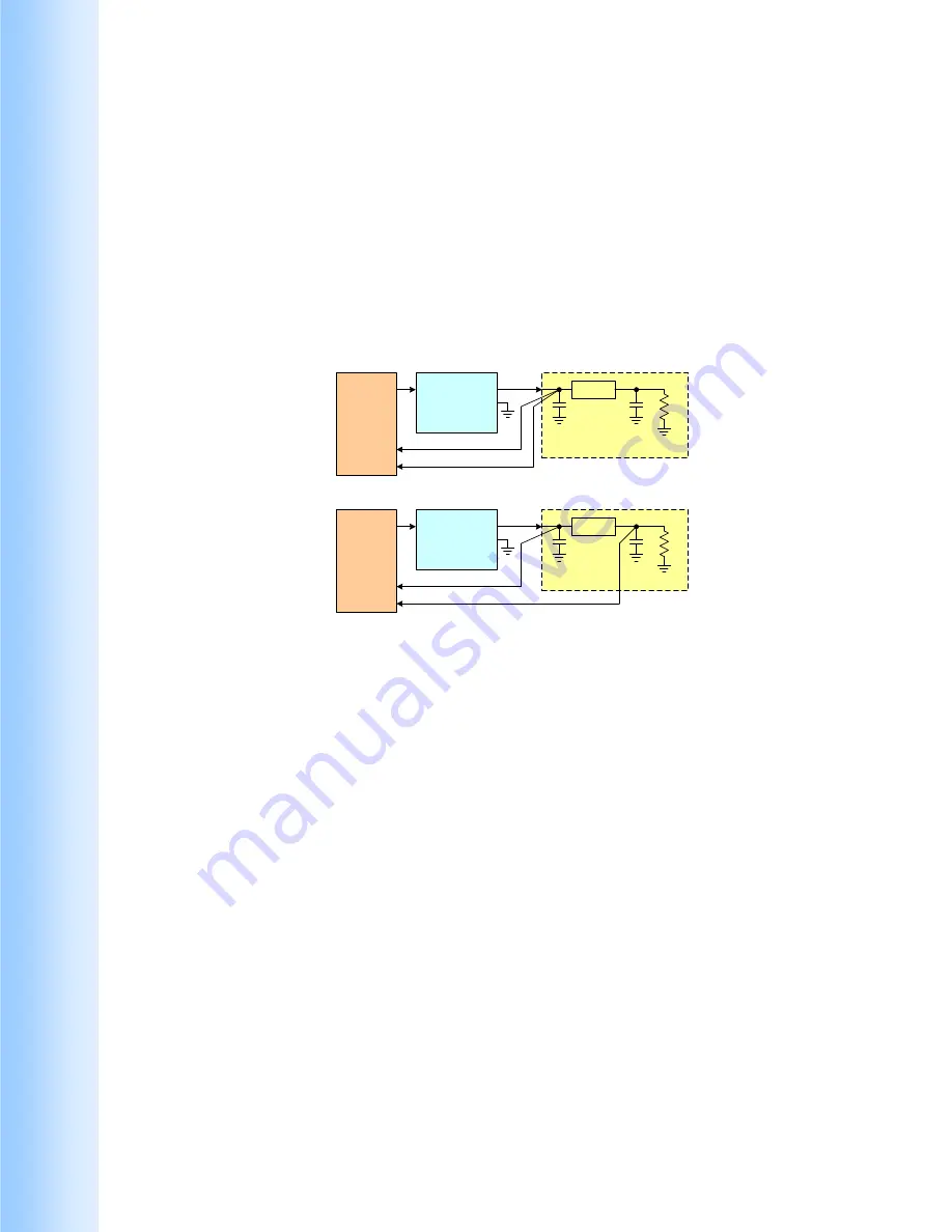
power amplifiers. PSRR measurement is easy with the aid of the TS200. Figure
3 shows how to measure PSRR. PSRR measurement technique involves a
network analyzer, TS200 power amplifier, and device under test (DUT).
LDO
Source
A
B
Network
Ananyzer
TS200
Mod
Input
Output
DUT
Load
LDO
Source
A
B
Network
Ananyzer
TS200
Mod
Input
Output
DUT
Load
(a)
(b)
Figure 3. LDO PSRR measurement setup. (a) Calibration setup, (b) PSRR setup.
Figure 3 shows the LDO PSRR measurement setup. Using a network analyzer,
the source is connected to the TS200 modulation input. The TS200 output is
connected to the LDO supply input. It is recommended to reduce the LDO input
capacitance to minimum. Since the TS200 can drive a heavy load, thus the
LDO output can be loaded with the desired loading resistor (i.e. maximum
specified load).
Set the TS200 modulation input to AC-coupled. Adjust the DC Offset knob
until the output DC voltage reaches the desired voltage (i.e. 3.3V). Typically
for PSRR measurement, the supply ripple amplitude is 200mVpp. If you are
using the A-version, set the network analyzer output to 200mV. If you are
using the B-version and consider the modulation gain is 20dB, set the network
analyzer output amplitude to 20mVpp.
First the network analyzer and the TS200 need to be calibrated. Figure 3a
shows the calibration setup. The network analyzer input-A and input-B are
connected together at one point on the DUT board near the LDO supply input.
Set the network analyzer to calibration mode and sweep over the frequency


