background image

T Series 

ConfigurationSetup Manual_Version 200807 

28

Motion Area Setup 

Motions in DVRs are defined as changes in image. Change in image is defined as change in 
color, since if an object or background color changes when object moves (e.g. person or car), or 
object changes in shape or color (e.g. blinking neon signs).  Motion areas are regions of image 
and a motion detection area is a specific region that is used for detecting motion. 
 
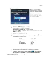
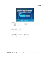
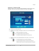
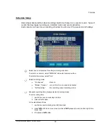
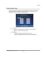
For motion detection in our DVRs, image is divided into grids (regions). The following picture 
show division of image and describes how to set detection in grid regions. 


Select camera by selecting camera number. 


Select sensitivity using scroll bar (

Sensitivity: Each grid region has many pixels. Positioning sensitivity marker near “-” means 
larger number of pixels (95% of pixels) need to change in color in order to be detected as a 
motion and positioning sensitivity marker near “+” means smaller number of (5% of pixels) 
need to change in color in order to be detected as a motion. 


Select motion detection area. Motion detection area is shown by “red” grid regions.  

To select an area,  

1.  move mouse to starting (top left) position of desired detection area; 

2. press 

left

 button and move mouse (while left 

left

 pressed) to end (bottom right) 

position of detection area; and 

3. lift 

(unpress) 

left

 button. 


To unselect the selected area. 

1.  move mouse to starting (top left) position of detection area; 

2. press 

right

 button and move mouse (while 

right

 button pressed) to end (bottom right) 

position of detection area; and 

3. lift 

(unpress) 

right

 button. 


4


3


2


1


Summary of Contents for T Series

Page 1: ...es ConfigurationSetup Manual_Version 200807 1 C Co on nf fi ig gu ur ra at ti io on n S Se et tu up p M MA AN NU UA AL L T T S Se er ri ie es s D Di ig gi it ta al l V Vi id de eo o R Re ec co or rd d...

Page 2: ...Time Sync 8 Disk Manager 10 User Account 11 Factory Default 14 System Shutdown 14 Device Setup 15 Camera Setup 15 Audio 19 Alarm Setup 19 Screen Display Setup 24 Recording Setup 26 Recording Mode Setu...

Page 3: ...ossible and only administrator can do this This item needs very careful control due to its status of system operation Search Recorded data can be searched by various type such as calendar search motio...

Page 4: ...ries ConfigurationSetup Manual_Version 200807 4 System Menu Structure Left diagram shows the menu structure of the system In this section we will describe Main Menu items System Device Record and Netw...

Page 5: ...an be obtained or changed in the system setup System name Virtual keyboard is appeared when selecting the left button of mouse in the system name input window and system name can be modified When syst...

Page 6: ...nal Type Signal type is shown for TV Video standard based on the region it belongs and this signal type is changed by NTSC PAL switch in the back panel Warning When signal type is changed the system m...

Page 7: ...listed holidays the holiday recording schedule will be applied See recording schedule set up Adding Holidays 1 Select holiday date in the calendar Select month using arrow button in the date selection...

Page 8: ...electing button Time Sync Time Sync ensures that DVR system time is always correct If Automatic Sync is selected and DVR is connected to a network DVR will retrieve current time from a time server and...

Page 9: ...T Series ConfigurationSetup Manual_Version 200807 9 DVR must be networked Time server time server must be active...

Page 10: ...CDRW DVDRW and USB Drives are listed Devices that are not recognized by the system are not listed All devices must be formatted before use Device Information 1 Select a device Total size free space de...

Page 11: ...formatted by DOS FAT up to 32G Bytes 3 Remove Button Visible when USB device is selected Click on this button before physically detaching un plugging USB cable USB device This safely closes all open f...

Page 12: ...user id password and permissions to perform certain operations can be set or unset Normal User Registrations Select a user e g USER1 in the user selection window Input user ID password password confir...

Page 13: ...e PTZ camera control Digital PTZ Allow user to use digital PTZ control Setup Allow user to set system configuration Shutdown Allow user to shutdown the system Search Allow user to search video events...

Page 14: ...nment variables to original default values When the system is reset to factor defaults it will prompt Select Yes and reboot System Shutdown This function allow the system to turn itself off graceful U...

Page 15: ...resolution and PTZ function can be set Brightness contrast and color are controlled by color control button Camera name recording frame number of each camera or all cameras and recording image resolut...

Page 16: ...imum resolution vs recording frame rate Select recording image quality High Sharpest image larger image size Medium Normal normal expected image size Low Low smaller image size Normal image resolution...

Page 17: ...ect by the right button of the mouse and setup each camera and select and confirm OK Activate menu by selecting dynamic PTZ tap Select the camera that is currently used by selecting PTZ device using s...

Page 18: ...Color Setup Setup the brightness contrast and saturation for the camera signal per camera Setup value is applied to the recording display mode To adjust color for a camera select the color control ta...

Page 19: ...deo channel allowing video and audio to be recorded together Select a camera to associate audio with video Select Not Use if audio will not be recorded Alarm Setup This alarm function is used for the...

Page 20: ...when this manual icon is selected Activate menu by selecting the sensor tab Enable or Disable sensor use Enable Use Enable Not Used Setup for the specific information about the sensor alarm Type Selec...

Page 21: ...elected Activate menu by selecting motion tab Enable or Disable sensor use Enable Use Enable Not Used Setup for the specific information about the sensor alarm Relay Select alarm relay port Dwell Sele...

Page 22: ...ted Setup is applied to the selected sensors when this manual icon is selected Activate menu by selecting the video loss tab Enable or Disable sensor use Enable Use Enable Not Used Setup for the speci...

Page 23: ...triggered On main screen one of the following icon will appear Blue HDD has enough space for the recording Yellow Recorded data capacity is approaching the limit Red Recorded data capacity has passed...

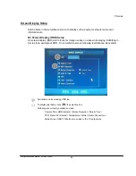
Page 24: ...or image overlay on video while playing Subtitling in movies is an example of OSD On surveillance screen following text data can be overlaid Activate menu by pressing OSD tab To display text data che...

Page 25: ...o can be displayed in sequence For each camera video is displayed for specified amount of time dwell time and then next camera video displayed Activate menu by pressing sequence tab For main monitor S...

Page 26: ...T Series ConfigurationSetup Manual_Version 200807 26 Recording Setup This section describe what and when image are recorded...

Page 27: ...ccurs and pre recording is set record 120 images frames preceding the alarm will be recorded Post Alarm Off No pre alarm recording On When alarm occurs and post recording is set record 60 seconds of v...

Page 28: ...Sensitivity Each grid region has many pixels Positioning sensitivity marker near means larger number of pixels 95 of pixels need to change in color in order to be detected as a motion and positioning...

Page 29: ...le To select one camera select MANUAL and select camera number To select all cameras select ALL Select recording mode Continuous Record Motion Sensor record if motion or sensor is activated No Recordi...

Page 30: ...igurationSetup Manual_Version 200807 30 Network Setup This section describe setting of IP MAC DNS address e mail notification for event occurrence web server port network port etc for communication vi...

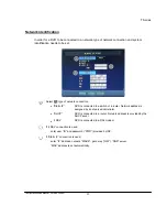
Page 31: ...on Static IP DVR is connected to a switch or a router Network address is assigned by a network administrator DHCP DVR is connected to a router Network address is provided by the DHCP sever xDSL DVR is...

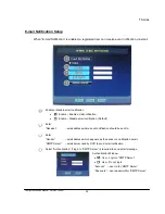
Page 32: ...ail notification Default Enter Receiver email address where event notification should be sent to Enter Sender email address which appears as the sender on notification email SMTP Server email server u...

Page 33: ...to connect to the system When dynamic IP address is used by the system e g DHCP or xDSL service unlike Static IP address IP address changes randomly e g DHCP assigns IP address for system and IP addr...

Page 34: ...Do not use DDNS service Default DDNS SITE DDNS server s domain name Currently supports servers ddnsin com no ip com and dyndns org DDNS Domain Unique subdomain name for the system on DDNS server DDNS...

Page 35: ...t if the service is enabled and IP address of remote client s PC is specified Remote client is identified by unique IP address Use or Not use Use Enable specified remote client PC to receive event not...

Page 36: ...T Series ConfigurationSetup Manual_Version 200807 36...

Reviews: