Chapter 3: Option Selection
FILTER RESPONSE SWITCH
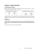
Filters are used to select input filtering on a channel-by-channel basis. When jumper FLT 0 is installed,
filtering is introduced for input BIT 0, FLT 1 for BIT 1, etc.
JUMPER SELECTION
Bit Filtered
JUMPER SELECTION
Bit Filtered
FLT-0
FLT-1
FLT-2
...
Bit 0
Bit 1
Bit 2
...
…
FLT-21
FLT-22
FLT-23
…
Bit 21
Bit 22
Bit 23
This filtering provides a slower response for DC signals as described previously and must be used when
AC inputs are applied. If you believe an input may be electrically noisy, install the jumper to avoid false
readings.
INTERRUPTS
Select the desired interrupt level by installing a jumper at one of the locations marked IRQxx. If IRQs are
enabled in software, an interrupt latch is set by the board when an Isolated Digital Input bit changes state.
A full description of how to enable/disable and clear IRQs is described in the Programming section of this
manual.
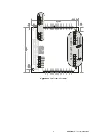
Refer to Figure 3-1 for more on filter and interrupt selection.
Manual 104-IDI-48 SERIES
10


