Manual 104-QUAD-8
21
Chapter 7: Specification
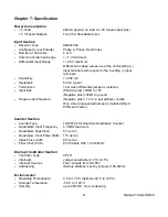
Power Consumption
+ 5 Volts
260mA (typical, no load on +5V fused output pins)
+ 5 V Fused Outputs
Two 0.5A Resettable fuses
Input Section
Receiver Type
AM26LS32
Configuration per Encoder
Phase A, Phase B and Index
Number of Channels
4 or 8
Common mode input range
+/- 7 V maximum
Differential Input Range
+/- 25 V maximum
Differential voltage values are at the noninverting (+)
input terminals with respect to the inverting (-) input
terminals
Sensitivity
+/- 200 mV
Hysteresis
50 mV typical
Termination
1k
Ω
when differential jumper is installed
Input bias
(Positive pins) 100
kΩ
to +5V
(Negative pins) 100k
Ω
to ground
Single-ended threshold
(Negative pins) +1.4V via pull up/down combo
Only when single-ended jumper is installed (Rev C
PCBs and newer)
Counter Section
Counter Type:
LS7267 24 bit Dual Axis Quadrature Counter
Quadrature Clock Frequency
4.3 MHz maximum
Quadrature Separation
57 ns min
Quadrature Clock Pulse Width 115 ns min
Index Pulse width
85 ns min
Filter Clock (FCK)
PC/104 Bus OSC 14.318 MHz
Interrupt Controller Section
Controller Type
CPLD
Interrupts
Jumper selectable (2-7,10-12,15)
Interrupt Sources
FLG1 outputs from LS7267
Addressing
ISA bus address is set by jumpers (100-3E0h)
Environmenta
l
Operating Temperature:
0
˚
C to +70
˚
C (optional -40
˚
C to +85
˚
C)
Storage Temperature:
-50
˚
C to +120
˚
C
Humidity:
up to 95% RH, non-condensing

