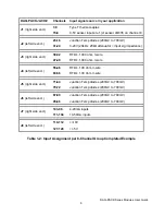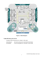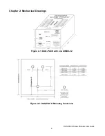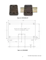
DAQ-PACK Series Modules User Guide
13
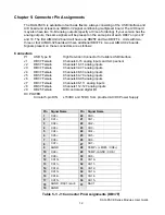
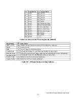
Pin
Signal Name
Pin
Signal Name
1
CH16+
20
CH16-
2
CH17+
21
CH17-
3
CH18+
22
CH18-
4
CH19+
23
CH19-
5
CH20+
24
CH20-
6
CH21+
25
CH21-
7
CH22+
26
CH22-
8
CH23+
27
CH23-
9
AGND
28
N/C
10
CH24+
29
CH24-
11
CH25+
30
CH25-
12
CH26+
31
CH26-
13
CH27+
32
CH27-
14
CH28+
33
CH28-
15
CH29+
34
CH29-
16
CH30+
35
CH30-
17
CH31+
36
CH31-
18
AGND / DAC0 return
37
DAC0
19
AGND
Table 5-2: J2 Connector Pin Assignments (DB37F)
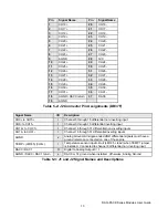
Signal Name
I/O
Description
CH0+ to CH15+
I
Channel 0 through 15 differential non-inverting input
CH0- to CH15-
I
Channel 0 through 15 differential inverting input
CH16+ to CH 31+
I
Channel 16 through 31 differential non-inverting inputs
CH16- to CH31-
I
Channel 16 through 31 differential inverting inputs
AGND
x
Analog Ground, All single-ended
AND
differential signals must have a
ground reference connected on one of these pins.
TEMP+ (LM335) (CH8+)
I
Temperature sensor input circuit (LM335 + lead) when TEMP1 jumper
is installed. Connected to channel 8 differential non-inverting input
DAC0 / DAC1
O
Digital to Analog Output 0 / 1
AGND / DAC0 / DAC1 return
x
DAC0 or 1's ground when installed. Otherwise, Analog Ground
Table 5-3: J1 and J2 Signal Names and Descriptions

