background image


ACCES I/O Products, Inc. 

MADE IN THE USA 

PCIe-ADIO16-16F Family Manual 


2


Rev B3d 

C

HAPTER 

1:


Q

UICK START


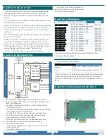
It is recommended that you install the software package before 
installing the PCI Express card in your computer.  Install the 

software

1

 using our stand-alone installer downloaded from the 

website. 
Run the installer you downloaded and follow the prompts to install 
the software for your device.   

Please note: during the installation you may be prompted regarding 

the installation of non-WHQL-certified drivers; please carefully 
confirm the digitally signed source of the drivers and accept the 
installation.   

Once the software has been installed, shut down your system and 
carefully install the card. 
Re-start your system.  Once the computer finishes booting, your 

new I/O should already be installed and ready for use; you can 
confirm this by launching Device Manager and looking under the 
“Data Acquisition” section.  If, for any reason, the device displays a 
warning triangle, right-click and select “Update Driver”. 

1

 In Linux or OSX please refer t

github.com/accesio/apci

. 

C

HAPTER 

2:


I

NTRODUCTION


PCI Express half-height/length with latching I/O connector 


2× 16-bit, Bipolar, Differential, A/D converters sampling at up to 

1MHz, simultaneously 


Software selectable as 16+0, 8+4, or 0+8 (Single-Ended + 

Differential Inputs) 


7 channel-by-channel programmable differential input ranges 

from ±0.3125V up to ±12V (48Vp-p) 


A/D starts via software, external input, or periodic timer 


A/D “Scan Start” mode optimizes inter-channel timing 


High impedance, 8-

channel input: 1 MΩ 


32k FIFO plus DMA for efficient, robust data streaming 


16× Digital I/O pins with flexible secondary functions 


Four 16-bit analog outputs 


5 per-channel programmable ranges: 0V to 5V, 0V to 10V, 

±2.5V, ±5V, ±10V 


Optional 4-20mA outputs 


Outputs Drive ±10mA Guaranteed 


Onboard Watchdog with status output 


RoHS compliant standard  


C

HAPTER 

3:


H

ARDWARE


This manual applies to the following models: 

VENDEV 

PCIe-ADIO16-16FDS 

A/D 16-bit, 2Msps,    4 D/A  

w/ timed DAC Waveform playback 

494F:C2EF 

PCIe-ADIO16-16F 

A/D 16-bit, 2Msps,    4 D/A 

494F:C2EC 

PCIe-ADIO16-16A 

A/D 16-bit, 1Msps,    4 D/A 

494F:C2ED  

PCIe-ADIO16-16E 

A/D 16-bit, 500Ksps, 4 D/A 

494F:C2EE 

PCIe-ADI16-16F 

A/D 16-bit, 2Msps 

494F:82EC 

PCIe-ADI16-16A 

A/D 16-bit, 1Msps 

494F:82ED 

PCIe-ADI16-16E 

A/D 16-bit, 500Ksps 

494F:82EE 

PCIe-ADIO12-16A 

A/D 12-bit, 500Ksps, 4 D/A 

494F:C25C 

PCIe-ADIO12-16 

A/D 12-bit, 250Ksps, 4 D/A 

494F:C25D 

PCIe-ADIO12-16E 

A/D 12-bit, 100Ksps, 4 D/A 

494F:C25E 

PCIe-ADI12-16A 

A/D 12-bit, 500Ksps 

494F:825C 

PCIe-ADI12-16 

A/D 12-bit, 250Ksps 

494F:825D 

PCIe-ADI12-16E 

A/D 12-bit, 100Ksps 

494F:825E 

All models are half-height and shorter-than-half-length cards. 
All units are RoHS compliant. 

INCLUDED IN YOUR PACKAGE  

1× PCIe-ADIO16-16F Family card  

Available accessories include: 

C68PS18L 


68-Pin SCSI 18” shielded cable with one-touch 

latches


STB-68


Screw Terminal Board (mounted on standoffs)


Contact the factory for information regarding additional accessories, 
options, and specials that may be available to best fit your specific 

application requirements, such as Industrial Temperature (-40°C to 
85°C).  
 

C

HAPTER 

4:


C

ONFIGURATION 

S

ETTINGS


Summary of Contents for PCIe-ADIO16-16A

Page 1: ...Sio com 10623 Roselle Street 800 326 1649 http accesio com PCIe ADIO16 16F San Diego CA 92121 1506 USA sales accesio com MADE IN THE USA 16 ANALOG INPUT 4 ANALOG OUTPUT 16 DIGITAL I O FOR PCI EXPRESS...

Page 2: ...A D Scan Start mode optimizes inter channel timing High impedance 8 channel input 1 M 32k FIFO plus DMA for efficient robust data streaming 16 Digital I O pins with flexible secondary functions Four 1...

Page 3: ...0 Ch 0 1 35 ADC IN 1 Ch 0 ADAS3022 1 ADC IN 2 Ch 1 3 37 ADC IN 3 Ch 1 ADC IN 4 Ch 2 5 39 ADC IN 5 Ch 2 ADC IN 6 Ch 3 7 41 ADC IN 7 Ch 3 ADC IN 8 Ch 4 9 43 ADC IN 9 Ch 4 ADC IN 10 Ch 5 11 45 ADC IN 11...

Page 4: ...CH0 1 0 Advanced Sequence Acquires Channel 0 using the gain selected via 18 bits 2 0 Conversion starts will automatically cycle through the channels from CH0 through INx2 0 and each channel is acquir...

Page 5: ...ol bit and status 4 W DAC Control DAC LTC2664 Command Register bits 8 W DAC Waveform Divisor DAC Waveform Points second divisor Base Clock DAC Waveform Rate this register C R ADC Base Clock Frequency...

Page 6: ...to their power on reset state see each ADC Register for more details RST BOARD Writing a 1 will reset the entire device to its power on reset state All RST bits are command bits a 1 causes the reset t...

Page 7: ...llion 125MHz but for broadest compatibility software should always read this register during init and always use the read value when calculating what if any divisor to write to the ADC Rate Divisor re...

Page 8: ...19 D18 D17 D16 D15 D14 D13 D12 D11 D10 D9 D8 D7 D6 D5 D4 D3 D2 D1 D0 Name RSV AIN 15 GAIN2 0 RSV AIN 14 GAIN2 0 RSV AIN 13 GAIN2 0 RSV AIN 12 GAIN2 0 RSV AIN 11 GAIN2 0 RSV AIN 10 GAIN2 0 RSV AIN 9 GA...

Page 9: ...rol 38 for important information about the Channel bits re Differential operation Diff SET indicates the paired ADC Counts were sampled in Differential mode Refer to ADC Control 38 for important infor...

Page 10: ...5 D9 D8 D7 D6 D5 D4 D3 D2 D1 D0 Name WDG UNUSED EXT1 EXT0 LDAC FOF FAF DTO DDONE ADCSTART ADCTRIG UNUSED enEXT1 enEXT0 enLDAC enFOF enFAF enDTO enDDONE enADCSTART enADCTRIG Read IRQ Status to determin...

Page 11: ...as a configurable active edge rising or falling SET the corresponding edgeXXX bit to select rising edge CLEAR the bit for falling edge IOGx SET each IOGx bit to configure the digital I O bits in the a...

Page 12: ...ave introduced a new source of latency the kernel userland division Application code runs in userland which must transition to the kernel in order to perform any hardware operation This transition add...

Page 13: ...all applicable EM interference and emission standards However as they are intended for use installed on motherboards and inside the chassis of industrial PCs important care in the selection of PC and...

Page 14: ...and invoiced COVERAGE FIRST THREE YEARS Returned unit part will be repaired and or replaced at ACCES option with no charge for labor or parts not excluded by warranty Warranty commences with equipmen...

Reviews: