Chapter 4: Address Selection
The board occupies 16 bytes of I/O space. The board base address can be selected anywhere within
the I/O address range 000-3F0. If in doubt where to assign the base address, refer to the following
tables and the FINDBASE program to find an available address for your system.
HexRange
Usage
000-00F
DMA Controller 1
020-021
INT Controller 1, Master
040-043
Programmable Interrupt Timer
060-06F
Keyboard Controller
070-07F
Real Time Clock, NMI Mask
080-09F
DMA Page Register
0A0-0BF
INT Controller 2
0C0-0DF
DMA Controller 2
0F0-0F1
Math Coprocessor
0F8-0FF
Math Coprocessor
170-177
Fixed Disk #1
1F0-1F8
Fixed Disk #2
200-207
Game I/O
238-23B
Bus Mouse
23C-23F
Alt. Bus Mouse
278-27F
Parallel Printer
2B0-2BF
EGA
2C0-2CF
EGA
2D0-2DF
EGA
2E0-2E7
GPIB (AT)
2E8-2EF
Serial Port
2F8-2FF
Serial Port
300-30F
Prototype Board
310-31F
Prototype Board
320-32F
Hard Disk (XT)
370-377
Floppy Controller #2
378-37F
Parallel Printer Port 1
380-38F
SDLC
3A0-3AF
SDLC
3B0-3BB
Monochrome Display/Printer
3BC-3BF
Parallel Printer Port 2
3C0-3CF
VGA EGA
3D0-3DF
CGA
3E8-3EF
Serial Port
3F0-3F7
Floppy Diskette Controller
3F8-3FF
Serial Port
Table 4-1:
Standard Address Assignments for Computers
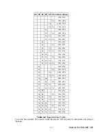
To set desired board address, refer to the illustrated Board Address setup program on the CD provided
with the board. Type the desired address in hexadecimal code and the graphic display shows you how
to set the Address Setup jumpers. These jumpers are marked A4-A9 and form a binary representation
of the address in negative-true logic. (assign '0' to all Address Setup jumpers placed ON the posts, and
assign '1' to all Address Setup jumpers left OFF.)
Manual 104-DIO-48E, 24E
12


