Page 3-1
Manual MPCI-ICM4S.F1b
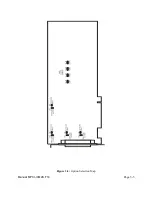
Figure 3-1:
Simplified Termination Schematic
Chapter 3: Option Selection
To help you locate the jumpers described in this section, refer to the Option Selection Map at the
end of this chapter. Operation is determined by jumper installation as described in the following
paragraphs.
Terminations
A transmission line should be terminated at
the receiving end in its characteristic
impedance. Installing a jumper at the
locations labeled LDO and LDI apply
120
S
loads across the transmit (LDO)and
receive (LDI) lines.
In operations where there are multiple terminals, only the ports at each end of the network should
have terminating impedance as described above. Also, for RS485 operation, there must be a bias
on the RX+ and RX- lines. If the PCI-ICM485 card is not to provide that bias in your application,
contact the factory.
Baud Rate Ranges
For each of the ports, jumpers labeled X1 and X4 provide means to select baud rates in either of two
ranges. When in the "X1" position, the baud rate range is up to 115,200 baud. When in the "X4"
position, the baud rate range is 200 to 460,800 baud. Refer to the Baud Rate Divisor Table on page
5-2 of the manual.
Interrupts
Please note that, in Windows NT systems, changes must be made to the system registry to support
IRQ sharing. The following is excerpted from "Controlling Multiport Serial I/O Cards"provided by
Microsoft in the MSDN library, documentid: mk: @ivt: nt40res/ D15/S55FC.HTM, also available
in the WindowsNT Resource Kit.
The Microsoft serial driver can be used to control many dumb multiport serial cards. Dumb
indicates that the control includes no on-board processor. Each port of a multiport card has a
separate subkey under the HKLM\CurrentControlSet\Services\Serial subkey in the registry. In each
of these subkeys, you must add values for DosDevices, Interrupt, InterruptStatus, PortAddress, and
PortIndex because these are not detected by the Hardware Recognizer. (For descriptions and ranges
for these values, see Regentry.hlp, the Registry help file on the WindowsNT Workstation Resource
Kit CD.)
Summary of Contents for PCI-ICM422/2
Page 2: ......
Page 16: ...PCI ICM422 2 4 and 485 2 4 Manual Page 2 6 Manual MPCI ICM4S F1b...
Page 19: ...Page 3 3 Manual MPCI ICM4S F1b Figure 3 2 Option Selection Map...
Page 20: ...PCI ICM422 2 4 and 485 2 4 Manual Page 3 4 Manual MPCI ICM4S F1b...
Page 22: ...PCI ICM422 2 4 and 485 2 4 Manual Page 4 2 Manual MPCI ICM4S F1b...
Page 28: ...PCI ICM422 2 4 and 485 2 4 Manual Page 6 2 Manual MPCI ICM4S F1b...
Page 32: ...PCI ICM422 2 4 and 485 2 4 Manual Page A 4 Manual MPCI ICM4S F1b...


