PCI-ICM422/2(4) and 485/2(4) Manual
Page 1-2
Manual MPCI-ICM4S.F1b
A crystal oscillator is located on the card. This oscillator permits precise selection of baud rates up
to 115,200 or, by changing a jumper, up to 460,800 with the standard crystal oscillator.
The driver/receiver used, the SN75176B, is capable of driving extremely long communication lines
at high baud rates. It can drive up to ±60 mA on balanced lines and receive inputs as low as a 200
mV differential signal superimposed on common mode noise of +12 V or -7 V. In case of
communication conflict, the driver/receivers feature thermal shutdown.
Communication Mode
PCI-ICM422/2 and PCI-ICM422/4 support Full-Duplex and Half-Duplex communications with a
4-wire cable connection. PCI-ICM485/2 and PCI-ICM485/4 support Half-Duplex communications
with a 2-wire cable connection. Half-Duplex allows traffic to travel in both directions, but only one
way at a time. RS485 communications commonly use the Half-Duplex mode since they share only
a single pair of wires and installation cost is reduced.
Baud Rate Ranges
The card has capability for two baud rate ranges, selectable on a port-by-port basis. One range is
for up to 115,200-baud applications and the other is for up to 460,800-baud applications. Refer to
Baud Rate Divisor Table on page 5-2 of the manual.
Auto-RTS Transceiver Control
In RS485 communications, the driver must be enabled and disabled as needed, allowing all cards to
share a 2-wire cable. The PCI-ICM485/2 and PCI-ICM485/4 cards control the individual drivers
automatically. With automatic control, the driver is enabled when data are ready to be transmitted.
The driver remains enabled after data transmission is complete for one additional character's
transmission time and then is disabled. The receiver is also normally enabled, then disabled during
RS485 transmissions, and then re-enabled after transmission is completed (plus that one character
transmission time). These cards automatically adjust their timing to the baud rate of the data. (The
automatic control feature makes the cards ideal for WIN95 applications)
Input/Output Connections
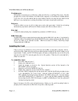
These cards use a 37-pin DBM connector and a breakout cable. The breakout cable terminates in
a DB9 connector for each port. Those DB9 connectors are equipped with 4-40 threaded standoffs
(female screw lock) to provide strain relief. The mating connector is AMP type 17D-E9s or
equivalent. We recommend using vinyl-jacketed, multiple, twisted-pair cable.
Summary of Contents for PCI-ICM422/2
Page 2: ......
Page 16: ...PCI ICM422 2 4 and 485 2 4 Manual Page 2 6 Manual MPCI ICM4S F1b...
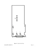
Page 19: ...Page 3 3 Manual MPCI ICM4S F1b Figure 3 2 Option Selection Map...
Page 20: ...PCI ICM422 2 4 and 485 2 4 Manual Page 3 4 Manual MPCI ICM4S F1b...
Page 22: ...PCI ICM422 2 4 and 485 2 4 Manual Page 4 2 Manual MPCI ICM4S F1b...
Page 28: ...PCI ICM422 2 4 and 485 2 4 Manual Page 6 2 Manual MPCI ICM4S F1b...
Page 32: ...PCI ICM422 2 4 and 485 2 4 Manual Page A 4 Manual MPCI ICM4S F1b...


