Page
6
of
17
Copyright © Access-IS 2020
2.2
Tool list
To install the VAL100, you will require the following tools:
•
Molex 63819-1000 22-28 AWG Crimp Tool
•
Molex 63819-0900 18-24 AWG Crimp Tool
•
Molex 11-03-0044 Crimp Extraction Tool
•
PZ2 Driver
•
T10 Driver
•
6 mm Drill Bit
•
25 mm Hole Saw
•
Deburring Tool
2.3
Cable requirements
The cables required to install the VAL100 are as follows:
Power cable
•
2-core 18 AWG, STRANDED
Ethernet cable (optional)
•
Cat 5e/Cat 6 USTP - 24 or 26 AWG, STRANDED
USB cable (optional)
•
USB 2.0 compatible cable - no longer than 4.5 metres
2.4
Pole mount procedure
Use the supplied pole mount kit to install the VAL100 on a pole in the vehicle. You can mount the
VAL100 on a 1.25 inch or 1.4 inch diameter pole.
Before starting this procedure, ensure that you have the correct mounting kit for the pole size that
you are using and the required tools and cables.
Refer to the
Installation drawings
(on page 13) if you need further help with installation procedure.
Warning: Ensure that the vehicle ignition is switched off during installation and when you attach the
VAL100 to the mounting bracket. Access-IS recommend that a 3 A fuse is connected in line with the
12/24 V supply cable.
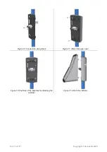
1. Wrap the drilling template around the pole.
Use the horizontal lines at the top and bottom of the template to ensure that the template is
aligned correctly.
2. Drill holes into the pole, as marked on the template. Three holes are required on the front face,
two holes on the back.
A 6 mm drill and 25 mm hole saw are recommended.
3. Deburr all holes inside and outside of the pole with a deburring tool.
4. Position the mounting bracket on the pole ensuring that the locating studs engage in the two
smaller holes in the front face of the pole.


