Page
7
of
17
Copyright © Access-IS 2020
4G only:
If you are using the 4G dongle, pass the provided USB dongle cable through the cable
aperture in the mounting bracket before carrying out this step. Make sure the USB cable passes
the pole on the right side (when looking at it from the front of the validator).
5. Position each pole clamp against the back of the pole and attach to the mounting bracket using
two M4 screws.
6. Thread the cables through the pole.
The cables must exit the pole through the 25 mm hole and provide sufficient slack for crimping.
7. Strip and crimp the ends of the cables.
8. Insert the crimps into the white connector block.
4G only:
The dongle cable comprises a 14-way white connector block, with a USB adapter
cable pre-wired into it, leaving 10 available pins to use for Ethernet and power. There is no
space for wiring another USB cable for other uses.
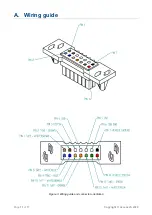
Refer to the
wiring guide
(on page 11) and note the orientation of the white connector block.
9.
4G only:
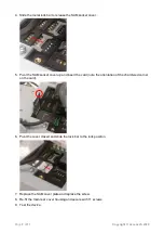
Position the USB dongle bracket over the three threaded studs on the mounting
bracket. Secure with an M4 nylon insert nut.
10.
4G only:
Secure the socket of the USB dongle cable to the USB dongle bracket using two M4 x
8 screws with captive washer.
11.
4G only:
Unpack the 4G USB dongle and load a Standard sized SIM card (also known as a Mini
SIM). Refer to the dongle’s quick start documentation for correct SIM loading instructions.
12.
4G only:
Insert the 4G USB dongle into the socket of the USB dongle cable. Ensure that the
dongle is inserted as far down as it will go. Fit the USB dongle clamp over the 4G USB dongle
lining up the holes with those in the USB dongle bracket. Secure the clamp with two M4 x 8
screws, tightening them fully.
13.
4G only:
Secure the ferrite of the USB dongle cable to its fixing position on the USB dongle
bracket using a ‘zip tie’.
14. Add sleeving or tape to the external sheath and clip the ferrite to the power cable, less than 100
mm from the connector.
It is recommended that you to
tie the cables together with a ‘zip tie’.
15. Push the white connector block into the connector bracket and secure the assembly to the
mounting bracket using two M4 screws.
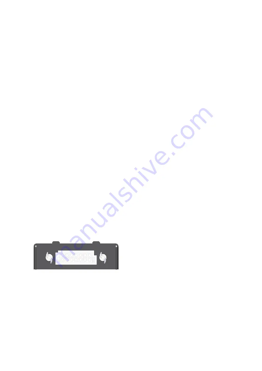
The following drawing shows the orientation of the connector.
Figure 2: Connector block orientation
16. Ensure the cables are positioned centrally, to avoid contact with any sharp edges, and carefully
feed back any slack wire.
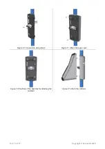
17. Fit the rear plastic cover and attach to the mounting bracket using four M3 screws (use a T10
Torx tool to secure the screws).
You can now fit the blanking plate or validator to the mounting bracket.
18. Locate the fixings on the back of the blanking plate or validator in the holes on the blanking plate
and slide down until fully engaged.
19. To secure the equipment, push in the security lock until it clicks.


