background image


GENERAL MAINTENANCE 


NOTE: Proper maintenance of the ATV is important for optimum 
performance.    Follow the Maintenance Schedule and all ensuing 
Maintenance Instructions/Information. 
 
If, at any time, abnormal noises, vibrations, or improper functioning of 
any component of this ATV is detected, DO NOT OPERATE THE ATV.   
Take the ATV to an authorized dealer for inspection and adjustment or 
repair. 
 
If the owner/operator does not feel qualified to perform any of these 
maintenance procedures or checks, take the ATV to an authorized ATV 
dealer for professional service. 
 
NOTE: The following instructions and information refer to specific items 
in the maintenance and care of the ATV. 

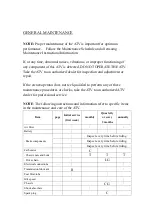
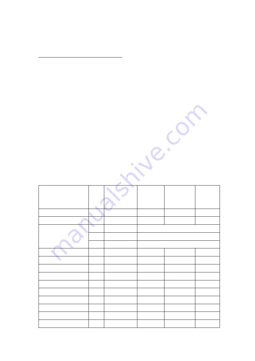
Item 

page 

Initial service 

(first week) 

monthly 

Quartetly 

or every 

3 months 

annually 

Air filter 


Battery 


Brake components 


Inspect every time before riding 


Inspect every time before riding 


Inspect every time before riding 

Carburetor 


Chassis nuts and bolts 


Drive chain 


I.G 


Electrical connections 


Transmission lubricant 


Fuel filter/tube 


Idle speed 


Chassis 


C.G 


Shock absorbers 


Spark plug 


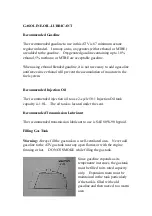
Summary of Contents for DRR 50

Page 1: ...Lubricant 8 Break in Procedure 9 GENERAL MAINTENANCE 10 20 Maintenance Schedule 10 Shock Absorbers 11 Cables 11 Transmission Lubricant 11 Hand Brake System 12 Adjusting Brakes 12 Protective Rubber Boo...

Page 2: ...that the child has the ability to operate the ATV safely Carefully read the following pages If you have any questions regarding this ATV contact an authorized ATV dealer for assistance Remember only...

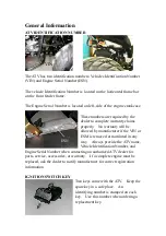
Page 3: ...y claims properly No warranty will be allowed by manufacturer if the VIN or ESM is removed or mutilated in any way Always provide the ATV name Vehicle Identification Number and Engine Serial Number wh...

Page 4: ...y compressing the brake levers toward the handle bar Brake Lever Locks To engage and release a brake lever lock use the following procedure 1 Compress the hand brake lever 2 Depress and hold the brake...

Page 5: ...engine The engine can be started again by pressing the yellow start button OFF position The ignition circuit is off The engine can not be started or will not run If the emergency stop switch is used...

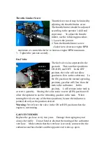
Page 6: ...ition the normal operating position gasoline will flow from the tank to the carburetor In this position L will remain in the tank as a reserve quantity Moving the valve to the reserve RES position wil...

Page 7: ...the seat is secure before mounting the ATV Severe personal injury may result if the seat is not properly secured SAFETY FLAG BRACKET A bracket is provided for mounting a flag at the rear at the rear...

Page 8: ...The recommended injection oil to use 2 cycle 50 1 Injection Oil tank capacity is 1 0L The oil tank is located under the seat Recommended Transmission Lubricant The recommended transmission lubricant...

Page 9: ...he engine RPM during the break in period allows the components to load aiding the engine component mating process and then unload allowing components to cool Although it is essential to place some str...

Page 10: ...d to perform any of these maintenance procedures or checks take the ATV to an authorized ATV dealer for professional service NOTE The following instructions and information refer to specific items in...

Page 11: ...cate the shock is in need of replacement cracks or breaks in the lower case or a bent shock rod If any one of these conditions is detected replacement is necessary CABLE None of the cables require lub...

Page 12: ...everse Brake Lever Locks Check to make sure the brake lever locks engage properly and that the brakes when engaged lock the wheels 1 Compress the left brake lever 2 Engage the brake lever lock 3 The r...

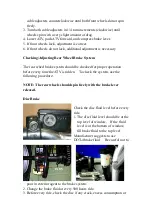
Page 13: ...uld be checked for proper operation before every time the ATV is ridden To check the system use the following procedure NOTE The rear wheels should spin freely with the brake lever released Disc Brake...

Page 14: ...dically Suspension Steering Arm assembly Right and Left 1 Secure the ATV on a support stand to elevate the front wheels 2 Remove both front wheels 3 Inspect the suspension steering arm assembly boots...

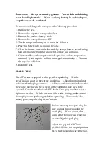
Page 15: ...cable to the negative terminal Connect the negative cable last 9 Install the seat SPARK PLUG The ATV comes equipped with a specified spark plug See the specifications chart for the correct spark plug...

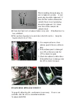
Page 16: ...uid The auxiliary liquid jar is located above the left rear tire Keep the liquid at the level of 150cc 1 Use compressed air to clean radiator panel if there is debris to plug 2 If the radiator panel i...

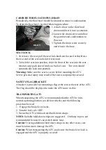
Page 17: ...to allow cable adjustment nut to be adjusted 3 Turn cable adjustment nut clockwise to increase free play in the cable Turn the adjustment nut counterclockwise to decrease free play in the cable 4 Ther...

Page 18: ...filter oil and work the oil into the element 7 Compress the element to remove excess oil 8 Clean any dirt or debris from inside the air cleaner Be sure no dirt enters the carburetor 9 Install the air...

Page 19: ...nt to use the proper tools when repairing or replacing tires to prevent damage to the tire bead or wheel rims If proper tools and related items are not available have this maintenance performed by an...

Page 20: ...lb by turning it clockwise while pushing in 4 Install the lens cover Caution Tighten the lens cover screws only until they are snug FUSE The main 7 5 Amp fuse is located on the frame near the battery...

Page 21: ...e engine and allow it to idle then using engine preserver rapidly inject the preserver into the air filter opening for a period of 10 to 20 seconds Install the air filter and housing cover Caution If...

Page 22: ...lubricant 5 Charge the battery then install 6 Connect the battery cables making sure to connect the positive cable first 7 Check the entire brake system cables shoes etc all controls and brakelight a...

Reviews: