background image

DL1000 

Product Manual 

DL1000, Rev 2.3 

Page 4 

Installation 

Powering The System: 

Always use a good solid power source.  To properly power the 

system: 
1.  Provide power from a dedicated power source for best results 

and to prevent power fluctuations. 

2.  Use the following chart for 

proper wire size and distance to 

the system.  Use U.L. listed wire 

with an insulation rating of 600 

volts.  When installed outdoors, 

use direct underground burial 

wire inside a conduit for best 

results. 

3.  Connect a 12-24VAC/VDC power 

source to the power terminals 

located on the right middle side 

of the circuit board. 


Basic Wiring Overview: 

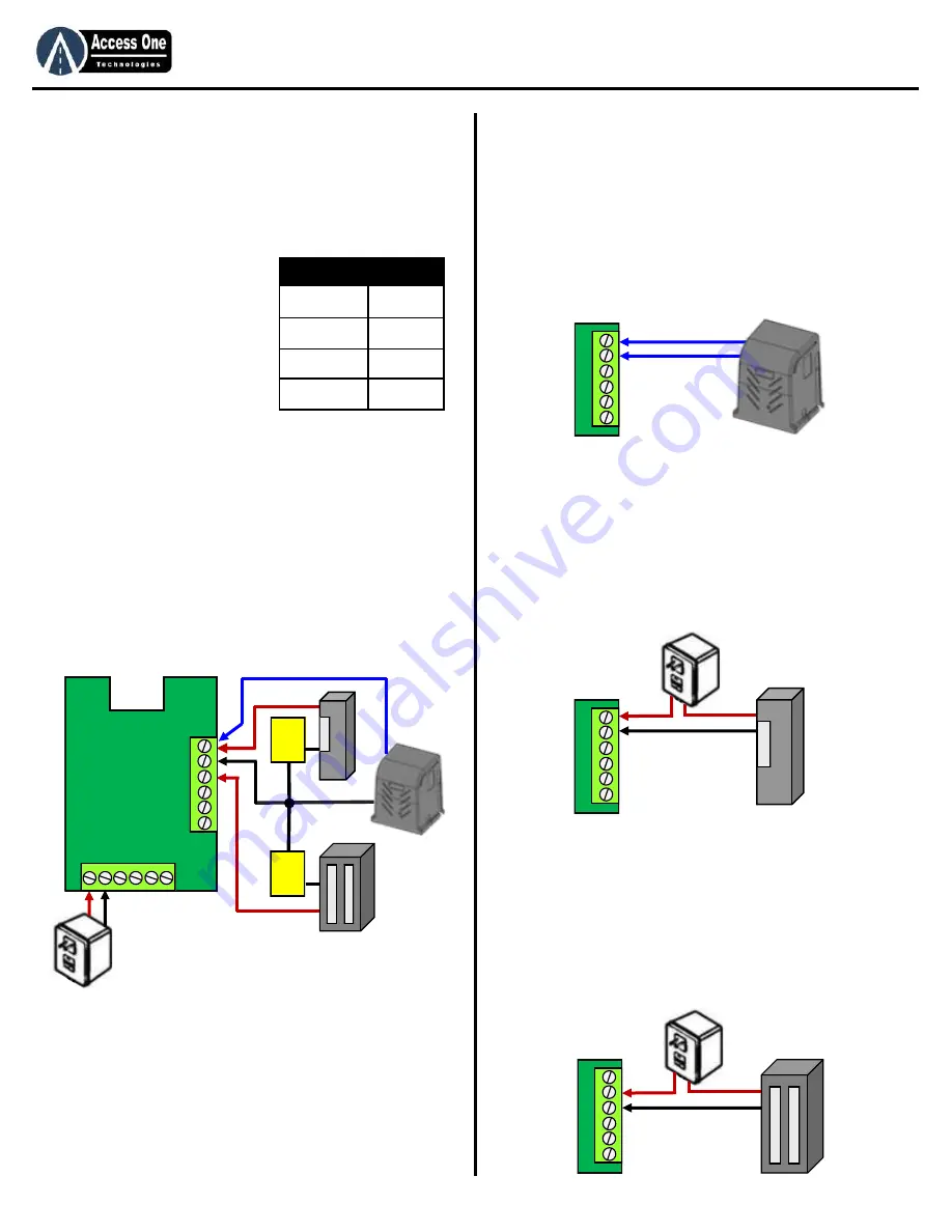
The DL1000 has two relays to control several types of devices.  To 

connect the DL1000 for basic use: 
1.  Connect a 12-24VAC/VDC power source to the Power 

Terminal. 

2.  Connect the activation device to the Relay 1 or Relay 2 inputs.  

There are NO, NC, and C inputs. 

3.  Connect bypass devices such as Postal Locks to the Exit 1 or 

Exit 2 inputs. 

4.  Connect Event devices such as loop detectors, wireless 

detectors to the Event input for controlled access. 


Installation 

Gate Operator Wire Connection: 

The system may be connected to an electric gate operator for gate 

access control.  When connecting to an electric gate operator, 

always follow the safety guidelines and precautions supplied with 

the gate operator.  To connect the system to a gate operator: 

1.  Connect NO1 to Gate Open Input. 
2.  Connect COM1 to Gate Common. 
3.  Use at least 18AWG or larger wire. 
4.  Important: Follow all safety guidelines and precautions when using 

the system with an automatic gate operator. 


Electric Strike Wire Connections: 

The system may be connected to an electric strike for pedestrian 

door or pedestrian gate control.  To connect the system to an 

electric strike: 

1.  Connect NO1 to the Strike power source. 
2.  Connect the Strike power source to the Electric Strike. 
3.  Connect COM1 directly to the Strike. 
4.  Use at least 18AWG or larger wire. 
5.  Important: A separate power source must be wired in series with the 

system and the Electric Strike.  Do not use the system supplied 

transformer to power the Electric Strike. 


Magnetic Lock Wire Connections: 

The system may be connected to an magnetic lock for pedestrian 

door or pedestrian gate control.  To connect the system to a 

magnetic lock: 

1.  Connect NC1 to the Magnetic Lock  power source. 
2.  Connect the Magnetic Lock power source to the Magnetic Lock. 
3.  Connect COM1 directly to the Magnetic Lock. 
4.  Use at least 18AWG or larger wire. 
5.  Important: A separate power source must be wired in series with the 

system and the Magnetic Lock.  Do not use the system supplied 

transformer to power the Magnetic Lock. 


Wire Size 

Distance 

18 AWG 

75 Feet 

16 AWG 

150 Feet 

14 AWG 

250 Feet 

12 AWG 

500 Feet 

Mag 

Lock 

Power 

Electric 

Strike 

Power 

12-24 AC/DC 

N

O

1

  C

   N

C

1

 N

O

2

  C

   N

C

2


GND


E

vn

E

xt

2


E

xt

1


12-24v 

N

O

1

  C

   N

C

1

 N

O

2

  C

   N

C

2


N

O

1

  C

   N

C

1

 N

O

2

  C

   N

C

2


N

O

1

  C

   N

C

1

 N

O

2

  C

   N

C

2


Summary of Contents for DL100

Page 1: ...ccess device Please refer to this manual and qualified personnel for assistance DO NOT install this device unless all entrapment and pinch points are eliminated 1 Revision 2 3 DL1000 Standalone Digita...

Page 2: ...Entry Codes 6 Add Single Customized Codes 7 Delete Single Entry Codes 8 Add Simple Block Entry Codes 8 Add Block Customized Codes 8 Delete Block Entry Codes 9 Auxiliary Input Programming 9 Entry Code...

Page 3: ...feature to prevent unauthorized use 8 Mount all operating devices clearly out of reach of through gates 9 DO NOT install this device unless all potential hazards and pinch points have been eliminated...

Page 4: ...m to a gate operator 1 Connect NO1 to Gate Open Input 2 Connect COM1 to Gate Common 3 Use at least 18AWG or larger wire 4 Important Follow all safety guidelines and precautions when using the system w...

Page 5: ...uxiliary Override inputs To activate Relay 1 1 Connect GND to the open device 2 Connect EXIT 1 to the open device To activate Relay 2 1 Connect GND to the open device 2 Connect EXIT 2 to the open devi...

Page 6: ...s serial number and PAC Serial Number Program Access Code Programming Time Clock Programming The DL1000 has a built in 7 Day Plus time clock for time control of individual codes and relay open schedu...

Page 7: ...date 21 Press or for active days of week All days Example 1 Sunday 246 MWF Programming Add Single Customized Code Cont 21 Press or for start time 12 00 00 Time is 12 hour format 22 Press for AM PM se...

Page 8: ...o customize an entry code settings program each step as needed To program a customized block of codes 1 Press and hold for 3 seconds until unit beeps STATUS 2 Press PAC PROGRAM 3 Press CODE 4 Press ST...

Page 9: ...gramming This programming will set the Relay Functions Event Control and Do Not Disturb DND control of the Auxiliary Inputs All external devices fire boxes key boxes pushbuttons connected to the Auxil...

Page 10: ...USERPREF 4 Press RESET 5 Press to confirm All codes will be cleared 6 Press to exit Turn power off on to reset Programming Strikes Lockout Programming Strikes Lockout helps prevent unauthorized users...

Page 11: ...M 2 PM 14 Press or for end time 12 00 00 Time is 12 hour format 15 Press for AM PM setting 1 AM 2 PM 16 Press or 1 6 for Relay 2 Function None 17 Press or 1 2 for Relay 2 Event Control Off 18 Press or...

Page 12: ...Feature The Do Not Disturb DND mode puts the system into a sleep mode and does not allow entry code or relay activation while DND is On active Entry codes that have been programmed with DND Access ON...

Page 13: ...trikes Lockout feature may be active Wait 3 minutes and retry 2 Make sure the keypad is plugged in correctly Entry Codes will not activate relay 1 Enter the entry code slower A beep should sound and s...

Page 14: ...can cause serious injury or death Read and follow all installation manuals reference manuals and warning label instructions 2 Vehicular gates are for vehicles only Pedestrians must use a separate entr...

Page 15: ...www AccessOneTechnologies com...

Reviews: