Access Tubs
5701 NW 35 Avenue Miami, FL 33142 PHONE: 877-249-2388 FAX: 866-560-1060 www.accesstub.com
Page 10
Access Tubs
DRAIN CONNECTION
To ensure safe transit for your walk-in tub, the overflow drain components are
not connected to the unit during the process of production. The following in-
structions are provided for installation purposes: Your walk-in tub is supplied
with a 1 ½” drain pipe overflow. The open and close valve with the turn knob
should be attached to the unit at the 1 ½” pre-drilled opening in the wall of the
unit from the outside. The opposite end of the overflow should be attached to
the 1 ½” pre-drilled opening in the foot well of the unit from the underside. The
chrome turn knob and the drain cover should be attached to the appropriate ends
of the overflow drain from the inside of the unit. Place the chrome cap with stem into
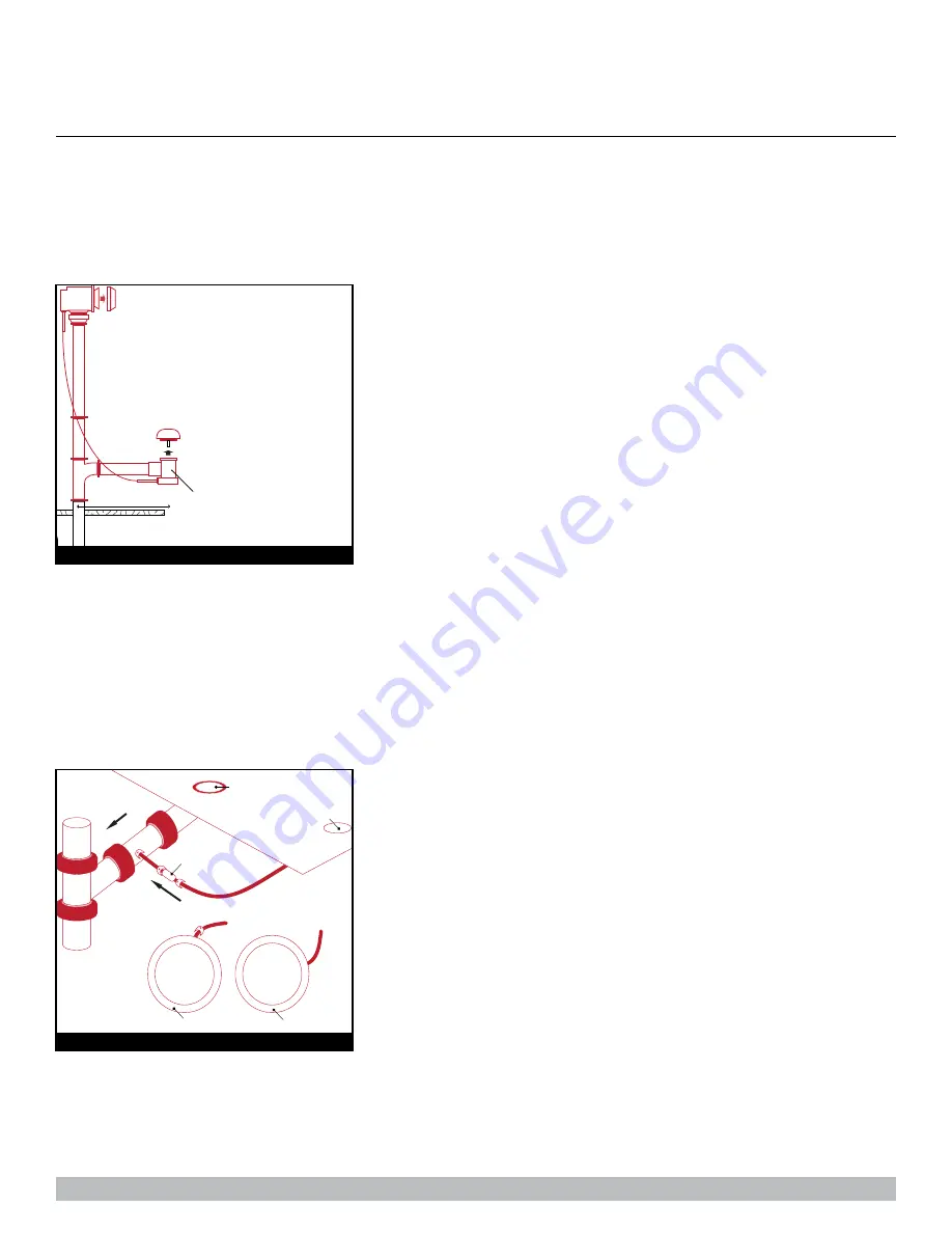
the floor drain to close off the opening. The cable attached to the turn knob of the overflow is also connected to a lever inside the floor drain
which allows the drain to be opened or closed. Once the components of the overflow are secured into place, turn the overflow knob to the
open and closed position to ensure proper function. The cap and stem will move up and down, opening and closing the drain (
Figure 1
).
Your walk-in tub also has a door drain to remove excess water from the door after
each use. From the underside of the unit, a hose is connected to the door drain with
a check valve. This hose and valve is to provide a one-way flow from the door drain
to the main drain pipe. The check valve will constrict the water flow away from the
door. Insert the opposite end of the hose into the port on the main drain. Be sure the
port is open before attaching the hose. Secure the hose with clamps or ties. Once
the hose is in place, close the door on the unit, place the handle in the locked posi-
tion, and fill tub with at least 12” of water to test the connection. Once the completion
of the drain components are installed and have been tested for proper function, the unit can be leveled and give a final water test
before installation of unit (
Figure 2
).
1 1/2” Door Drain Pipe supplied
7 1/2”
FIGURE 1
Floor Drain
Incorrect
Flow
Door Drain
Correct
Check Valve
Flo
w
FIGURE 2
OPERATING INSTRUCTIONS


