background image

Opening your life

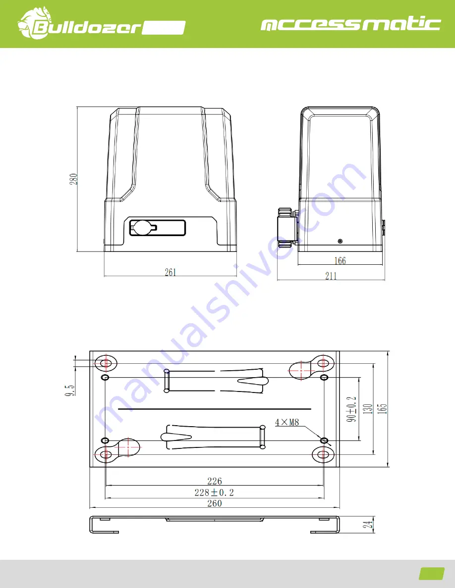
4.2 Dimensiones 
4.2.1 Dimensiones del motor 

4.2.2 Dimensiones del soporte inferior 

FIG.2

FIG.3

824

5

Summary of Contents for Bulldozor 824

Page 1: ...oducto La instalaci n de su nueva puerta debe ser realizada por una persona t cnicamente calificada o licenciada Tratar de instalar o reparar el motor sin tener la calificaci n t cnica puede resultar...

Page 2: ...ning your life 824 CONTENIDO Instrucciones de seguridad Lista de empaque Especificaciones t cnicas Instalaci n Conexi n y ajuste de la tarjeta de control Mantenimiento Soluci n de problemas 1 3 3 4 5...

Page 3: ...o realice cambios de partes a menos de que el manual lo indique Cualquier cambio que no se encuentre indicado pueden generar errores de funcionamiento Cualquier da o en el producto ocasionado por algu...

Page 4: ...oporte Llaves Control remoto Caja de acccesorios Perno hexagonal M8X60 Tuerca M8 Arandela 8 Arandela de presi n 8 CANTIDAD IMAGEN NOMBRE Motor Soporte Llaves Control remoto Caja de acccesorios Perno h...

Page 5: ...motor El motor debe instalarse dentro de un compartimiento para mayor proyecci n MODELO BD824 110V 60Hz Voltaje de entrada Potencia Velocidad Peso m ximo de la puerta Alcance del control remoto Final...

Page 6: ...Opening your life 4 1 Esquema de la instalaci n FIG 1 824 4 1 Motor 2 Teclado inal mbrico 3 Puerta 4 Sensor fotocelda 5 L mpara 6 Tope mec nico 7 Cremallera 8 Control remoto...

Page 7: ...Opening your life 4 2 Dimensiones 4 2 1 Dimensiones del motor 4 2 2 Dimensiones del soporte inferior FIG 2 FIG 3 824 5...

Page 8: ...r por debajo del suelo y dentro de un tubo de PVC o el material que la regulaci n local exija Haga uso de tubos independientes para el cable de control y el de alimentaci n Pedestal de concreto Aseg r...

Page 9: ...3 3 Instalaci n de la cremallera Asegure los tornillos de sujeci n a la cremallera Ubique la cremallera sobre el pi n externo del equipo aseg rese que la cremallera encaje con el pi n antes de soldar...

Page 10: ...Opening your life Verifique si hay un espacio adecuado entre la cremallera y el pi n FIG 7 FIG 8 FIG 7 Cremallera Pi on externo 824 8...

Page 11: ...ctrico en un lugar accesible La altura m nima es de 1 5m para evitar que los ni os puedan manipular lo Despu s de instalar verifique las propiedades mec nicas del equipo y la puerta Aseg rese de que...

Page 12: ...ta de control y el men L1 L5 Rojo Indican las configuraciones par metros y errores Botones de configuraci n PROG Entrar o salir del men de programaci n o Ajuste y selecci n de par metros SET Ajustar l...

Page 13: ...econozca el l mite de manera autom tica despu s suelte el bot n para detenerse Al presionar los botones o el l mite de apertura se puede ajustar de manera precisa e Oprima el bot n SET para confirmar...

Page 14: ...a est conectada los indicadores se encender n durante 1 segundo El aprendizaje habr finalizado 3 La tarjeta de control se saldr del modo de programaci n despu s de que grabe correctamente un control r...

Page 15: ...a los botones 3 y 4 del control programado durante 3 segundos La l mpara empezar a parpadear lo que indica que el modo de aprendizaje inteligente est iniciando 2 Oprima el bot n del control remoto que...

Page 16: ...otones 3 y 4 del control programado durante 3 segundos La l mpara empezar a parpadear lo que indica que el modo de aprendizaje inteligente est iniciando 2 Oprima el bot n del control remoto que desea...

Page 17: ...adores LED L1 a L5 mostrar n la configuraci n actual Por defecto se encuentra desactivada y todos los indicadores estar n apagados 3 Oprimaelbot n o paraprogramarlasensibilidaddelosobst culo Losindica...

Page 18: ...esLEDL1aL5mostrar neltiempodecierreautom ticoprogra mado El tiempo por defecto es con todos los indicadores apagados 4 Oprima los botones o para programar el tiempo de cierre autom tico El n mero de i...

Page 19: ...leado o en las fotoceldas Si no hay accesorios conectados aseg rese de hacer un puente entre los puertos IR y COM Si hay accesorios conectados aseg rese de que los cables est n bien y como NC Hay un p...

Page 20: ...ing the product The installation of your new door must be carried out by a technically qualified or licensed person Attempting to install or repair the motor without technical qualification can result...

Page 21: ...Opening your life 824 CONTENT Security instructions Packing list Technical specifications Installation Control card connection and adjustment Maintenance Troubleshootings 1 3 3 4 5 5 6...

Page 22: ...on Please do not change any parts except for those defined under this manual Any undefined changes may cause the malfunction Any damages to the product arising therefrom shall be beyond the liability...

Page 23: ...Opening your life 2 Packing List standard 824 2 1 2 3 4 4 1 4 2 4 3 4 4...

Page 24: ...tallation The BD824 sliding door motor is ideal for doors less than 800Kg and 12m wide The drive system engages the rack and pinion of the motor The engine should be installed inside a compartment for...

Page 25: ...Opening your life 4 1 Installation diagram 1 Motor 2 Wireless keyboard 3 Door 4 Sensor photocell 5 Lamp 6 Mechanical stop 7 Gear rack 8 Remote control FIG 1 824 4...

Page 26: ...Opening your life 4 2 Size of Main Machine and Accessories 4 2 1 Size of Main Machine 4 2 2 Size of Mounting Plate FIG 2 FIG 3 824 5...

Page 27: ...installation Inordertoguaranteethenormaloperationofthegateopenerandprotectthecablesfromdamages pleaseburythemotorpowercable and controlling cable separately with two PVC tubes Concrete pedestal Please...

Page 28: ...open the manual release bar till it opens to 90 as shown in Figure 5 Then rotate the output gear and the gear can be rotated easily 4 3 3 Gear Rack Installation Fix the mounting screws to the gear rac...

Page 29: ...Opening your life The fit clearance of output gear and rack is shown in Figure 7 below FIG 7 FIG 8 FIG 7 824 8...

Page 30: ...nually moved before installing the main machine Please note that for this product one control can only drive one main machine otherwise the control system will be damaged Earth leakage circuit breaker...

Page 31: ...ating the control board working status and menu status L1 L5 Red Indicating the settings parameters and errors Setup Buttons PROG Enter into or exit the setting menu and Functions selection and parame...

Page 32: ...he limit position c Press SET button to confirm the closing limit position The indicator lights will be on in sequence from L1 to L5 3 Gate Opening Limit Position Setting d Press and hold button to en...

Page 33: ...tton which is to be learned on the remote control Indicator lights L1 L5 will be on for 1 sec If an alarm lamp is connected it ll be on for one sec Learning is finished 3 The control board will exit l...

Page 34: ...a los botones 3 y 4 del control programado durante 3 segundos La l mpara empezar a parpadear lo que indica que el modo de aprendizaje inteligente est iniciando 2 Oprima el bot n del control remoto que...

Page 35: ...neously press and hold the third and fourth buttons of the programmed remote control for 3 sec The alarm lamp will flash which indicates that the learning function of the control board is on working 2...

Page 36: ...tor light L0 will flicker once then L1 will be always on 2 Press SET button once to enter into setting mode Indicator lights L1 L5 will show the current setting The default is without this function an...

Page 37: ...er once and then L1 will be always on 2 Press button once to enter into Auto close setting option Indicator light L2 will be always on 3 Press SET button once to enter into setting Indicator lights L1...

Page 38: ...safety each gate is suggested to be equipped with infrared protector besides which regular inspection is required Before installation and operation of the gate opener please read all instructions car...

Page 39: ...Opening your life 824 18...

Page 40: ...Opening your life www accessmatic com...

Reviews: