background image

Opening your life

www.accessmatic.com

Opening your life

9

Code: 

RP120

Raptor

Programming instructions

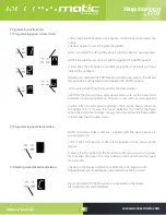
a) Press and hold SET Button until 1 appears on the display then release the 

button.

The door opener is now in Programming Mode.

b) Press and hold the UP until the door reaches the desired  open position.  


NOTE: Fine adjustments can be made by toggling UP &DOWN buttons

c) Now press the SET button to confirm the position. The display will now 

indicate the number 2.

d) Next press and hold the DOWN button until the door reaches the desired 

close position. For fine adjustments toggle UP & DOWN buttons.

 e) Now press the SET button to confirm the close position.

CAUTION: The door will now cycle open and close to set the travel limits 

and force sensitivity adjustments. The door is now set for normal operation.

Caution: After the cycle opens and closes, there will be figures shown on 

the display (0-9). “0” means the door is balanced, the smaller the figure 

means the better door balance, strongly recommend that the figure needs 

to be smaller than the power force. 

NOTE: Hand transmitters that are supplied with the door opener are 

pre-programmed.

a) Press the CODE button. A dot will be indicated in the corner of the 

display.

b) Now press the button on the hand transmitter you want to use, pause 

for 2 seconds, then press the same button on the hand transmitter again 

for 2 seconds.

The dot on the display will flash to confirm the code, then turn off.

Repeat the process for additional remotes that need to be stored.

1) Programming open & close limits

2) Programming hand transmitters

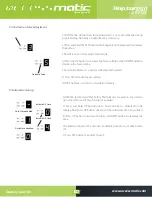
3) Deleting stored hand transmitters

Press and hold CODE button until a C is indicated on the display.

All stored remotes will be deleted.

Summary of Contents for Raptor 120

Page 1: ...r favor lea el manual detenidamente antes de la instalaci n el uso del producto La instalaci n de su nueva puerta debe ser realizada por una persona t cnicamente calificada o licenciada Tratar de inst...

Page 2: ...ducto Recomendaciones previas a la instalaci n Instrucciones de instalaci n Instalaci n v a de acero Instalaci n conjunto de riel de acero seccional Conjunto de bater a de respaldo opcional Instruccio...

Page 3: ...anquilidad adicional 6 Aseg rese de que la puerta del garaje est completamente abierta y parada antes de entrar o salir del garaje 7 Aseg rese de que la puerta del garaje est completamente cerrada y p...

Page 4: ...instalaci n deben incluir detalles para la instalaci n del variador y sus componentes asociados Descripci n y caracter sticas del producto 1 Reversa de seguridad autom tica La parada autom tica retro...

Page 5: ...ales para garantizar que pueda controlar 4 puertas diferentes con un transmisor 12 Espacio para la cabeza inferior Con tan solo 30 mm necesarios entre el techo y el punto m s alto del recorrido de la...

Page 6: ...pared interior Depende del espacio de instalaci n real Soporte de la puerta fije el soporte de la puerta a una parte estructural de la puerta lo m s cerca posible del borde superior Figura 3 Instalac...

Page 7: ...evante y apoye el cabezal del abridor con una escalera para que quede en posici n central y nivelada Fije el abridor y el riel en el techo mediante el soporte de hierro A y B ADVERTENCIA Nopermitaquel...

Page 8: ...ueda dentada luego todo el riel ensamblado terminado 1 Riel de 2 partes Como se muestra en la Figura 7 deslice el riel A en la manga deslice el riel B en la manga Pista de 3 partes Como se muestra en...

Page 9: ...n los tornillos suministrados PASO 2 Figura 14 Une la bater a al motor encuentra la Figura 14 Figura 10 Figura 12 Figura 11 Conjunto de bater a de respaldo opcional Opci n 1 Superior fijo solo para ba...

Page 10: ...iciar el abre puertasdegaraje PD Reiniciarsignificaquetodaslasconfiguracionesvuelvenalaconfiguraci ndef brica todaslascosasdeaprendizaje debenhacersenuevamente exceptoelc digodeaprendizajedeltransmiso...

Page 11: ...ablecer los l mites de recorrido y los ajustes de sensibilidad de la fuerza La puerta ahora est configurada para operaci n normal Precauci n Despu s de realizar los ciclos de apertura y cierre el disp...

Page 12: ...se puede ajustar hacia arriba c Presione SET para confirmar su configuraci n NOTA La fuerza se establece en 3 como est ndar en la f brica 4 Ajuste de la fuerza de obstrucci n 5 Cierre autom tico NOTA...

Page 13: ...ci n de haz de fotos presione ARRIBA nueva mente la pantalla indicar una H habilitada o presione el bot n ABAJO para deshabilitar pantalla 11 la opci n b Presione SET para confirmar el conjunto 6 haz...

Page 14: ...pondientes para esta funci n y proporcionan voltaje de luz de flash de 24v 35v Conecte la luz del flash con DC 24v 28v current 100mA Cuando use luces de flash de alimentaci n de CA de 110V combine un...

Page 15: ...jo Figura19 Tiredelasaparadesengancharlalanzade ra Para volver a activar la puerta simplemente haga funcionar el abridor en modo autom tico o mueva la puerta con la mano hasta que el carro encaje en l...

Page 16: ...ositivos de seguridad funcionen eficazmente haces de fotos etc 2 Cambio de bombilla Aviso aseg rese de que se haya cortado la fuente de alimentaci n antes de reemplazar la bombilla Y aseg rese de que...

Page 17: ...Capacidad de almacenamiento de c digos Terminal de precuaci n de l z Temperatura de trabajo Protecci n de seguridad Nivel de protecci nl r RP 120 1200 N 18 0 130kg 2400 3500mm Cadena Cintur n 160mm Se...

Page 18: ...a de panel de control 1 Cubierta de panel de control 2 Cubierta principal Bombillo L E D 1 PCB 1 PCB 2 Motorreductor DC Manga de eje de motor Transformador Item Soporte final de pista Soporte de pared...

Page 19: ...y kaka Pantalla digital H El cable entre el motorreductor y el tablero est desconectado Abra la tapa y compruebe la conexi n del cable entre el motor de engranajes y tablero 4 El abridor se de tiene a...

Page 20: ...puede usar o la distancia de operaci n es corta 1 bater a baja 2 La antena est suelta o no est bien extendida 3 Interferencia alrededor 1 Reemplace por una bater a nueva 2 Extender la antena en el mot...

Page 21: ...or de la reparaci n o repuesto s requerido s Cualquier reparaci n correctiva en partes mec nicas tendr garant a de 3 meses y el ctricas de 1 mes No aplica para reparaciones hechas por alguien diferent...

Page 22: ...uctoen el sitio de instalaci n garantizando las condiciones de uso 3 Si durante los primeros 5 d as despu s de la compra el equipo presenta fallas en su funcionamiento que se relacionen a defectos de...

Page 23: ...r com co para acceder a los beneficios de la garant a en el momento de instalar el producto 1 Cuando se evidencie da os por descargas el ctricas o rastros de corto circuito por variaciones de voltaje...

Page 24: ...NING Please read the manual carefully before installation using the product The installation of your new door must be carried out by a technically qualified or licensed person Attempting to install or...

Page 25: ...uct Description Features Pre Installation Recommendations Installation instructions Installation SteelTrack Installation Sectional SteelTrack Assembly Battery backup Assembly optional Programming Inst...

Page 26: ...that the garage door is fully open stationary before driving in or out of the garage 7 Make sure the garage door is fully closed stationary before leaving 8 Keep hands and loose clothing off the open...

Page 27: ...ards We are circumspect to protect your children pet or other goods 2 Soft start Soft stop Ramping speed up and down at the start and end of each cycle reduces stress on the door and opener for longer...

Page 28: ...DOWN UP DOWN Moving up Moving down B Pre installation recommendations 1 Garage door must be able to be lifted and closed easily by hand and without much effort A well balanced sprung door is critical...

Page 29: ...igure 3 Wall Bracket Close the garage door and measure the garage door width at the top and mark the centre Locate and mount the wall bracket 2cm 15cm above the door on the inside wall Depend on the a...

Page 30: ...5 Lift and support the opener head with a ladder so it is positioned centrally and level Fix the opener and track on ceiling by Iron bracket A B WARNING Do not allow children around the door opener o...

Page 31: ...hread on sprocket then whole rail assembled finished 1 2 PartsTrack As Figure 7 slide the A rail into the sleeve slide the B rail into the sleeve 3 PartsTrack As Figure 8 slide the C rail into the sle...

Page 32: ...attery only STEP 1 Figure11 Assemble the battery the bracket like the photo fix by screws supplied STEP 2 Figure12 Join the battery to opener find the Figure 12 Option 2 Side Fixed For Lead acid Lithi...

Page 33: ...or opener will restart PS Restart means all settings are back to factory settings all learning things need to be done again except the transmitter learning code Short press a In the Setting Status sho...

Page 34: ...nts The door is now set for normal operation Caution After the cycle opens and closes there will be figures shown on the display 0 9 0 means the door is balanced the smaller the figure means the bette...

Page 35: ...Press SET to confirm your setting NOTE The force is set on 3 as standard in factory 4 Obstruction force adjustment 5 Automatic closing NOTE We recommend that Safety Photo Beams be used in any install...

Page 36: ...on until 11 appears on the display To enable the photo beam option press UP again the display will indicate a H enabled or press DOWN button to disable display 11 the option b Press SET to confirm the...

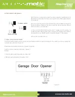
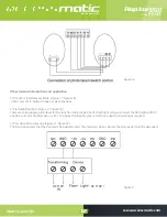
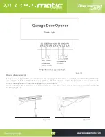
Page 37: ...h light function Figure 17 Figure 18 There are corresponding interfaces for this function and provide 24v 35v flash light voltage Connect the flash light with DC 24v 28v current 100mA When use AC 110V...

Page 38: ...gage shuttle and move door by hand while holding the handle down Figure 19 Pull on the handle to disengage the shuttle To re engage the door simply run opener in automatic mode or move door by hand un...

Page 39: ...e sure that the safety devices are working effectively photo beams etc 2 Light bulb replacing Notice Make sure the power supply has been cut off before replacing the light bulb And ensure the voltage...

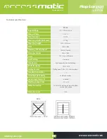
Page 40: ...Limit setting Transformer Radio frequency Coding Format Standard transmitter Code Storage Capacity Caution light terminal Working temperature Safety Protection Protection level r 1200 N 18 0 130kg 240...

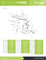
Page 41: ...0 31 Qty Item Item L E D cover Control panel cover 1 Control panel cover 2 Main cover L E D light PCB 1 PCB 2 DC Gear motor Motor Shaft Sleeve Transformer Item Track ending bracket Wall bracket Door b...

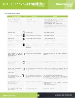
Page 42: ...lace the control board or power board When remoting the door opener stops automatically after running 10cm Digital display Hall sensor wire is loosed or damaged Open the cover check the Hall sensor wi...

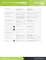
Page 43: ...tion distance is short 1 Flat battery 2 Antenna is loosed or not well extended 3 Interference around nearby 1 Replacenewbattery 2 Extendedtheantennaontheopener 3 Getridofinterference Cannot code in th...

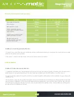
Page 44: ...t be granted and the customer must pay the value of the repair or spare part s required Any corrective repair in mechanical parts will have a 3 month warranty and a 1 month electrical warranty Does no...

Page 45: ...t the installation site guaranteeing the conditions of use 3 If during the first 5 days after the purchase the equipment presents malfunctions that are related to manufacturing defects the product wil...

Page 46: ...ess the benefits of the warranty at the moment of installing the product 1 When there is evidence of damage due to electrical discharges or short circuit traces due to voltage variations on site which...

Page 47: ...Opening your life www accessmatic com Opening your life www accessmatic com Opening your life www accessmatic com...

Reviews: