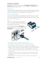
7
www.acclaimlighting.com
Fu
se
25
0V
/8A
V
+
V
+
R
e
d
-
G
re
e
n
-
B
lue
-
W
h
it
e
-
1
Fu
se
25
0V
/8A
V
+
V
+
R
e
d
-
G
re
e
n
-
B
lue
-
W
h
it
e
-
2
Fu
se
25
0V
/8A
V
+
V
+
R
e
d
-
G
re
e
n
-
B
lue
-
W
h
it
e
-
3
Fu
se
25
0V
/8A
V
+
V
+
R
e
d
-
G
re
e
n
-
B
lue
-
W
h
it
e
-
4
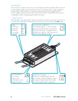
1=
Gr
ou
nd
2 =
D A
TA
-
3 =
D A
TA
+
DM
X/
RD
M
OU
T
3
2
1
AN
AL
OG
IN
0-1
0V
/1-1
0V
GND
DA
LI
IN
DA
DA
D M
X /
R D
M
I N
3
2
1
Fu
se
25
0V
/8A
V
+
V
+
R
e
d
-
G
re
e
n
-
B
lue
-
W
h
it
e
-
1
Fu
se
25
0V
/8A
V
+
V
+
R
e
d
-
Green
-
B
lue
-
White
-
2
Fu
se
25
0V
/8A
V
+
V
+
R
e
d
-
G
re
e
n
-
B
lue
-
W
h
it
e
-
3
Fu
se
25
0V
/8A
V
+
V
+
R
e
d
-
Green
-
B
lue
-
Whit
e
-
4
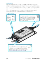
1=
Gr
ou
nd
2 =
D A
TA
-
3 =
D A
TA
+
DM
X/
RD
M
OU
T
3
2
1
AN
AL
OG
IN
0-1
0V
/1-1
0V
GND
DA
LI
IN
DA
DA
D M
X /
R D
M
I N
3
2
1
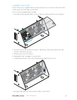
CONNECTOR COVER
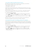
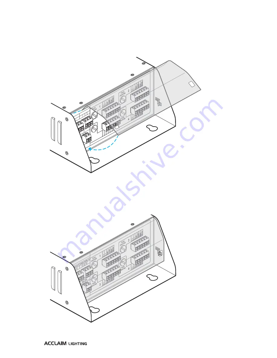
Each AL Driver unit is supplied with a transparent plastic cover to provide protection to the
control inputs and port output connections.
TO FIT THE CONNECTOR COVER
1 Insert the angled upper lip of the cover into the slot at the top of the connector panel.
2 Lower the lower edge of the cover down so that the two holes align with the two clips
located on the driver side walls.
3 Carefully clip the cover into place.
TO REMOVE THE CONNECTOR COVER
1 Carefully release the two clips and swing the lower edge of the cover up.
2 Disengage the upper lip of the cover from the AL Driver frame.

