7
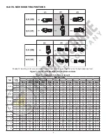
FOR 3-PIECE COUPLED INPUT REDUCERS (Reference Figure 3)
FOR CLAMP COLLAR INPUT REDUCERS (Reference Figure 4)
View the coupling assembly through the access hole in the C-face adapter.
1. Make sure the couplings jaws fully engage the spider. If they do not, loosen
the setscrew in the reducer coupling half and slide it forward until full jaw
engagement is achieved. However, make sure the jaws on one coupling half
do not contact the hub of the other coupling half.
2. Reaching through the access hole in the C-face adapter with a hex
key, tighten the coupling setscrew on the reducer coupling half to the
recommended torque given below.
View the clamp collar through the access holes in the C-face adapter.
1. Rotate the clamp collar to locate the setscrew over the key, if necessary.
2. Tighten the setscrew to the torque referenced below.
3. Reach through the access hole in the C-face adapter with a hex socket and
tighten the clamp collar clamping bolt to the torque value given below.
Replace the access hole plugs in the C-face adapter.
Replace the access hole plugs in the C-face adapter.
NOTE: A TEE handle hex key wrench is not stiff enough to properly
tighten the coupling setscrews. A large diameter socket wrench
extension with a short hex key insert must be used in conjunction with a
torque wrench. Failure to tighten the setcrews to the proper torque may
result in movement between shafts and coupling components and cause
premature wear on the shafts, coupling and keys.
NOTE: A TEE handle hex key wrench is not stiff enough to properly
tighten the clamp collar bolt. A socket wrench extension with a hex
insert must be used in conjunction with a torque wrench. Failure to
tighten the clamp collar to the proper torque may result in movement
between motor and reducer shafts and cause premature wear on the
shafts and keys.
FOR 3-PIECE COUPLED INPUT REDUCERS
Reference Figure 3
FOR CLAMP COLLAR INPUT REDUCERS
Reference Figure 4
NEMA
Motor
Frame
Coupling
Size
Setscrew
Size
Setscrew
Tightening Torque
Motor Coupling
Half Position
Dimension “X”
NEMA
Motor
Frame
Clamp
Bolt
Clamp Bolt
Tightening Torque
Setscrew
Size
Set Screw
Tightening Torque
56
19
M5
18 lb-in (2 Nm)
0
56
M6
132 lb-in (15 Nm)
M4
27 lb-in (3 Nm)
140
19/24
M5
18 lb-in (2 Nm)
0
140
M6
132 lb-in (15 Nm)
M4
27 lb-in (3 Nm)
180
24/28
M5
18 lb-in (2 Nm)
0
180
M8
312 lb-in (35 Nm)
M6
90 lb-in (10 Nm)
210
28/38
M6
42 lb-in (4.8 Nm)
0
210
M10
600 lb-in (68 Nm)
M8
220 lb-in (25 Nm)
250
38/45
M8
90 lb-in (10 Nm)
0
250
M8
312 lb-in (35 Nm)
M6
90 lb-in (10 Nm)
280
42/55
M8
90 lb-in (10 Nm)
0
280
M8
312 lb-in (35 Nm)
M6
90 lb-in (10 Nm)
320
48/60
M8
90 lb-in (10 Nm)
0
320
M10
600 lb-in (68 Nm)
M8
220 lb-in (25 Nm)
360
55/70
M10
150 lb-in (17 Nm)
0
360
M10
600 lb-in (68 Nm)
M8
220 lb-in (25 Nm)
IEC
Motor
Frame
Coupling
Size
Setscrew
Size
Setscrew
Tightening Torque
Motor Coupling
Half Position
Dimension “X”
IEC
Motor
Frame
Clamp
Bolt
Clamp Bolt
Tightening Torque
Setscrew
Size
Set Screw
Tightening Torque
71
19
M5
18 lb-in (2 Nm)
0
71
M6
132 lb-in (15 Nm)
M4
27 lb-in (3 Nm)
80
19/24
M5
18 lb-in (2 Nm)
0
80
M6
132 lb-in (15 Nm)
M4
27 lb-in (3 Nm)
90
19/24
M5
18 lb-in (2 Nm)
0
90
M8
312 lb-in (35 Nm)
M6
90 lb-in (10 Nm)
100
24/28
M5
18 lb-in (2 Nm)
0
100
M8
312 lb-in (35 Nm)
M6
90 lb-in (10 Nm)
112
24/28
M5
18 lb-in (2 Nm)
0
112
M8
312 lb-in (35 Nm)
M6
90 lb-in (10 Nm)
132
28/38
M6
42 lb-in (4.8 Nm)
0
132
M10
600 lb-in (68 Nm)
M8
220 lb-in (25 Nm)
160
38/45
M8
90 lb-in (10 Nm)
0
160
M8
312 lb-in (35 Nm)
M6
90 lb-in (10 Nm)
180
42/55
M8
90 lb-in (10 Nm)
0
180
M8
312 lb-in (35 Nm)
M6
90 lb-in (10 Nm)
200
42/55
M8
90 lb-in (10 Nm)
0
200
M10
600 lb-in (68 Nm)
M8
220 lb-in (25 Nm)
225
48/60
M8
90 lb-in (10 Nm)
0.040 in (6.0 mm)
250
55/70
M10
150 lb-in (17 Nm)
0
WARNING: The DODGE QUANTIS ILH and its connected
equipment and accessories must be guarded. Rotating parts
such as couplings, pulleys, fans and unused shaft extensions
must be permanently guarded by the user against accidental
contact with personnel and their clothing. The surface
temperature of the DODGE QUANTIS ILH enclosure may
reach temperatures which can cause discomfort or injury to
personnel accidentally coming into contact with hot surfaces.
The user should provide guards to prevent accidental
contact with hot surfaces. Guards must be sufficiently rigid
to maintain adequate guarding in normal service.
WARNING: Threaded hardware used to mount the DODGE
QUANTIS ILH Unit must be SAE Grade 5 or Metric Class 8.8
or better. DO NOT USE HARDWARE OF A LOWER GRADE.
MAINTENANCE
Check oil levels and oil quality regularly. Change oil at the intervals
specified in the Lubricants section of this document. Check
alignments of drive components regularly. Check chain and belt
tensions and hardware tightness periodically too.
Summary of Contents for LOUDEN 200 Series
Page 1: ......
Page 2: ......
Page 3: ......
Page 4: ......
Page 5: ......
Page 6: ......
Page 7: ......
Page 8: ......
Page 9: ...FIGURE 8 FIGURE 9 FIGURE 10 FIGURE 11...
Page 10: ......
Page 11: ......
Page 12: ......
Page 13: ......
Page 14: ......
Page 15: ......
Page 16: ......
Page 17: ......
Page 18: ......
Page 19: ......
Page 20: ......
Page 21: ......
Page 22: ......
Page 23: ......
Page 24: ......
Page 25: ......
Page 26: ......
Page 27: ......
Page 28: ......
Page 29: ......
Page 30: ......
Page 31: ......
Page 32: ......
Page 33: ......
Page 34: ......
Page 35: ......
Page 36: ......
Page 37: ......
Page 38: ......
Page 39: ......
Page 40: ......
Page 41: ......
Page 42: ......
Page 43: ......
Page 44: ......
Page 45: ......
Page 46: ......
Page 47: ......
Page 48: ......
Page 49: ......
Page 50: ......
Page 51: ......
Page 52: ......
Page 53: ......
Page 54: ......
Page 55: ......
Page 56: ......
Page 57: ......
Page 58: ......
Page 59: ......
Page 60: ......
Page 61: ......
Page 62: ......
Page 63: ......
Page 64: ......
Page 65: ......
Page 66: ......
Page 67: ......
Page 68: ......
Page 69: ......
Page 70: ......
Page 71: ......
Page 72: ......
Page 73: ......
Page 74: ......
Page 75: ......
Page 76: ......
Page 77: ......
Page 78: ......
Page 79: ......
Page 80: ......
Page 81: ......
Page 82: ......
Page 83: ......
Page 84: ......
Page 85: ......
Page 86: ......
Page 87: ......
Page 88: ......
Page 89: ......
Page 90: ......
Page 91: ......
Page 92: ......
Page 93: ......
Page 94: ......
Page 95: ......
Page 96: ......
Page 97: ......
Page 98: ......
Page 99: ......
Page 100: ......
Page 101: ......
Page 102: ......
Page 103: ......
Page 104: ......
Page 105: ......
Page 106: ......
Page 107: ......
Page 108: ......


