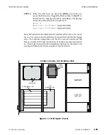
STEP 3:
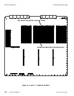
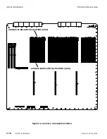
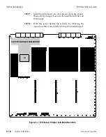
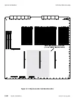
Note the orientation notch in J6 and orient the replacement
Wipe Generator sub-board to match. Seat the sub-board on
the connector and press gently but firmly directly over the
connector area so as not to unduly flex the Switcher board.
Fix the standoff fastening screws to secure the sub-board. Use
the Accom supplied tool to reseat the Switcher board in the
8150 Signal Chassis.
STEP 4:
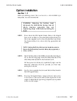
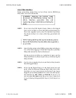
Power up the Signal Chassis. Perform wipes on the M/E and
PGM/PST buses to verify proper operation. Select the
SuperMatte generator as a source and adjust it to verify that
it is present.
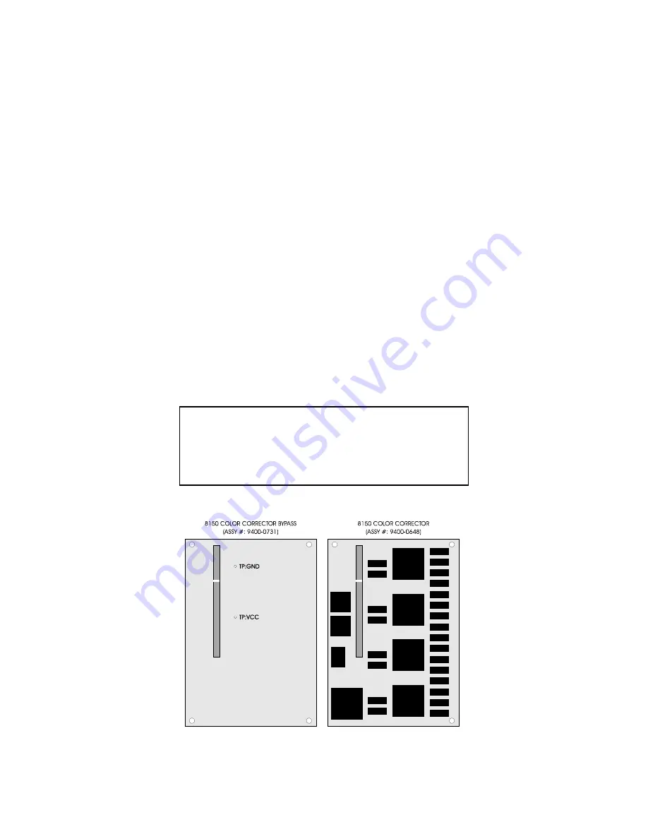
Color Corrector/Color Corrector Bypass
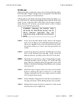
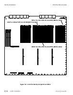
Before proceeding, ensure that you have the correct sub-board; the Color
Corrector board is Accom P/N 9400-0648; the Color Corrector Bypass
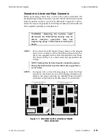
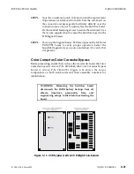
board is Accom P/N 9400-0731. Figure 3-13 shows the major
components on both sub-boards and their assembly numbers for
identification.
WARNING: Removing the Switcher board
disconnects the RAM battery backup. Save all
effects, timelines, personality files, and
engineering setups to disk before extracting the
board.
Figure 3-13 CCR Bypass (Left) & CCR (Right) Sub-Boards
8150 Technical Guide
Option Installation
9100-0212-04 - May 2000
Option Installation
3-21
Summary of Contents for ASWR8150
Page 12: ...Table of Contents 8150 Technical Guide X Contents 9100 0212 04 May 2000...
Page 39: ......
Page 80: ...Control Panel Connector Detail 8150 Technical Guide 2 40 Installation 9100 0212 04 May 2000...
Page 109: ...Option Installation 8150 Technical Guide 3 30 Option Installation 9100 0212 04 May 2000...
Page 236: ...8150 Partial Parts List 8150 Technical Guide A 6 Appendix 9100 0212 04 May 2000...

