STEP 15:
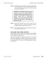
Reconnect the two power harnesses and the Power Fail cable
to the Motherboard. The 12-way connector mates with J16,
the 16-way connector mates with J17, and the two-way
connector mates with J20.
WARNING: The Motherboard has male mating
connectors for the circuit board assemblies.
Though the connectors are designed to prevent
insertion if the Circuit Board connectors are not
properly aligned with the Motherboard
connectors, use caution when inserting board
assemblies into the chassis. They should not
require a great deal of force, and should slide
smoothly into place.
STEP 16:
Reinstall the Switcher board into the chassis. Use the
inserter/extractor tool to seat the circuit board connectors
completely into the Motherboard connectors.
STEP 17:
Power up the 8150 Signal Chassis and replace the front panel.
The unit is now ready for use.
Power Supply Output Voltage Adjustment
It is probably not necessary, but you can adjust the power supply’s
output voltages as follows. Perform this adjustment when the power
supply is outside the Signal Chassis.
This procedure requires a digital volt-ohm meter, an insulated
screwdriver or alignment tool, a method to connect AC mains power to
the AC input terminals, and a user supplied low resistance load to
connect across the +/-12V outputs for use in bringing the power supply
into regulation.
8150 Technical Guide
Assembly Removal /Replacement
9100-0212-04 - May 2000
Engineering Setup
5-67
Summary of Contents for ASWR8150
Page 12: ...Table of Contents 8150 Technical Guide X Contents 9100 0212 04 May 2000...
Page 39: ......
Page 80: ...Control Panel Connector Detail 8150 Technical Guide 2 40 Installation 9100 0212 04 May 2000...
Page 109: ...Option Installation 8150 Technical Guide 3 30 Option Installation 9100 0212 04 May 2000...
Page 236: ...8150 Partial Parts List 8150 Technical Guide A 6 Appendix 9100 0212 04 May 2000...

