Section 6
System Timing
General Timing Considerations
Introduction
Using digital processing in a post production switcher lets you
implement features that would be difficult, or at least very expensive,
with a traditional analog switcher. Because the video is processed
digitally, you can use features such as automatic input timing, key and
border defocus, wide keyer borders, vertical key sizing and positioning,
and high resolution 4:4:4 chroma key extraction and downsampling.
This processing, however, does take time. The processing delay for the
Preview and Program outputs is a minimum of 34 lines; however, with
the optional Frame Delay Output module, which is optional on the 8100
and standard on the 8150, you can select either the 34-line delay (from
reference) or a full frame of delay for the Program 1 and Preview outputs
so that you can retime them into your system. The Program 2 output
delay is fixed at one frame from reference.
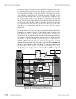
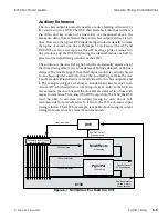
There are three timing delays associated with the 8150 Aux bus outputs:
two lines from reference, 18 lines from reference, and 34 lines from
reference. Additionally, you can select a one frame delay for the Aux 1
and 2 pair only; a detailed discussion of these three delays appears
below. Most devices that a typical post production switcher must feed,
however, are not affected by these delays. Monitors, as long as they are
set to internal sync, simply lock to their input video regardless of its
timing relative to the rest of the system. Likewise, routing switchers and
other terminal gear usually are not concerned with the relative timing
of their input video sources. Most VTRs and digital disk recorders
automatically lock to their input video when in Record or Edit mode,
and relock to external reference when in playback mode. Also,
component digital VTRs with the "preread" or "read before write"
feature typically allow up to 40 lines of external processing delay.
Most DVEs do not correctly lock to video more than one to two lines
delayed from the DVE reference. For this reason, the 8150 provides a
floating reference output associated with each pair of Aux outputs. This
floating reference is called Aux(iliary) Ref(erence), and it matches the
timing of its associated Aux outputs so that any destination device locks
8150 Technical Guide
General Timing Considerations
9100-0212-04 - May 2000
System Timing
6-1
Summary of Contents for ASWR8150
Page 12: ...Table of Contents 8150 Technical Guide X Contents 9100 0212 04 May 2000...
Page 39: ......
Page 80: ...Control Panel Connector Detail 8150 Technical Guide 2 40 Installation 9100 0212 04 May 2000...
Page 109: ...Option Installation 8150 Technical Guide 3 30 Option Installation 9100 0212 04 May 2000...
Page 236: ...8150 Partial Parts List 8150 Technical Guide A 6 Appendix 9100 0212 04 May 2000...

