Auxiliary Reference
The Aux bus output is normally used as a router, feeding video and/or
key sources out to a DVE. The DVE then feeds back into the switcher as
the video and key source of a linear key. As mentioned above, the
minimum delay from reference that an Aux bus output can have is two
lines. However, the typical DVE input timing window is usually no more
than plus or minus one line with respect to reference (the A57 and
DVEOUS are two an exceptions, the A57 having a plus or minus two
line window, and the DVEOUS having the identical minus one half to
plus two line input timing window as the 8150).
The solution is the Aux Ref signal, which automatically selects one of
the three timing offsets: two lines delayed, 18 lines delayed, or 34 lines
delayed. The Aux Ref signal from the Output module is vertically timed
to Aux bus outputs 1 and 2 (if active); the Aux Ref 2 signal from the Aux
3 and 4 module (if installed) is vertically timed to Aux bus outputs 3 and
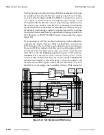
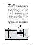
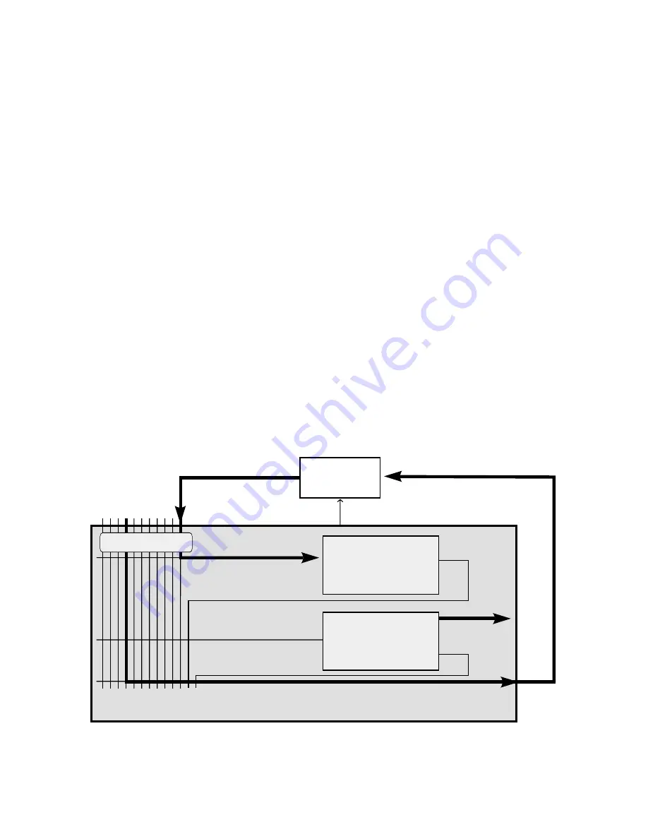
4. The example in Figure 6-1 shows a standard Aux bus feed out to an
Accom A57, which returns to an 8150 input as a re-entry to the M/E. In
this example, the Aux bus and the Aux Ref are delayed two lines with
respect to reference. To re-enter the DVE output into the 8150, the DVE
must be able to advance its output timing by only about 10.5
microseconds from its reference to fall into the 8150 automatic input
timing window. The A57, for example, is capable of advancing its output
timing from reference by almost 19 microseconds.
DVE
8150
"Aux Ref" Output
2 lines delayed
Automatic Input Timing
(up to 2-line delay)
Video and Key
2 lines delayed
Pgm/Pst Output
34 lines delayed
Aux Bus Outputs
(Video & Key)
2 lines delayed
Mix/Effects
16-line delay
Pgm/Pst
16-line delay
18 lines total delay
18 lines total delay
Figure 6-1 Normal Aux Bus Feed to a DVE
8150 Technical Guide
General Timing Considerations
9100-0212-04 - May 2000
System Timing
6-5
Summary of Contents for ASWR8150
Page 12: ...Table of Contents 8150 Technical Guide X Contents 9100 0212 04 May 2000...
Page 39: ......
Page 80: ...Control Panel Connector Detail 8150 Technical Guide 2 40 Installation 9100 0212 04 May 2000...
Page 109: ...Option Installation 8150 Technical Guide 3 30 Option Installation 9100 0212 04 May 2000...
Page 236: ...8150 Partial Parts List 8150 Technical Guide A 6 Appendix 9100 0212 04 May 2000...


