Signal Chassis Connections
Video Inputs
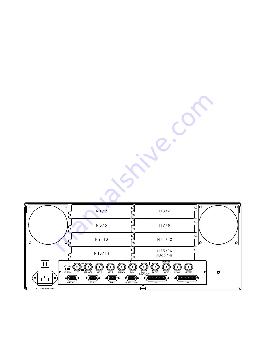
Inputs 1 - 14
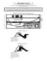
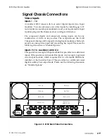
A standard 8150 comes with four serial digital inputs (two Input
modules). You can customize your video inputs by installing up to 12
more inputs (six more Input modules) to meet your requirements. Input
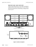
modules plug into the chassis as shown in Figure 2-5, below.
The component digital and component analog inputs can be any
combination of video or key sources. The exceptions are the 10-bit
Component Analog and Composite Analog Input modules, which each
accept one analog video input and one analog key input. Please see the
following discussion on "Module Options."
Inputs 15/16 - Auxiliary (AUX) 3/4
This position can accept an Input module that provides two additional
inputs. If the position is not needed for inputs, it can accept an optional
Aux Output module, which requires that two Delaystik SIMMs be
installed on the Switcher board. This provides two additional serial
digital auxiliary bus output feeds. Please see the following discussion
on "Module Options."
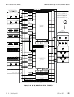
Figure 2-5 8150 Back Panel Connections
8150 Technical Guide
Signal Chassis Connections
9100-0212-04 - May 2000
Installation
2-9
Summary of Contents for ASWR8150
Page 12: ...Table of Contents 8150 Technical Guide X Contents 9100 0212 04 May 2000...
Page 39: ......
Page 80: ...Control Panel Connector Detail 8150 Technical Guide 2 40 Installation 9100 0212 04 May 2000...
Page 109: ...Option Installation 8150 Technical Guide 3 30 Option Installation 9100 0212 04 May 2000...
Page 236: ...8150 Partial Parts List 8150 Technical Guide A 6 Appendix 9100 0212 04 May 2000...

