Section 3
Option Installation
This section explains how to identify and install 8150 options and
sub-assemblies. The 8150 is configured at the factory, but you may
upgrade your system later, or you may need to identify installed options.
Some option sub-boards plug into the 8150 Main board with standoff
supports. Others are SIMM type plug-ins. Still others plug into the rear
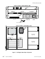
of the chassis or attach to the interior of the chassis. Figure 3-1, on the
following page, shows the Main and DVE board locations in the 8150
Signal Chassis. Remove the integral front cover/air filter to access the
boards.
WARNING: Removing the Main board
disconnects the RAM battery backup. Save all
effects, personality files, and engineering
setups to disk before extracting the board.
Use the Accom supplied tool to extract boards from the chassis. Lay the
board(s) on a clean, static free, grounded work surface.
NOTE: See the instructions at the front of this manual.
Observe all static electricity precautions you would
normally follow when handling static sensitive electronic
components. Handling the 8150 Main Switcher or DVE
boards (or the sub-boards) casually may cause failure.
8150 Technical Guide
9100-0212-04 - May 2000
Option Installation
3-1
Summary of Contents for ASWR8150
Page 12: ...Table of Contents 8150 Technical Guide X Contents 9100 0212 04 May 2000...
Page 39: ......
Page 80: ...Control Panel Connector Detail 8150 Technical Guide 2 40 Installation 9100 0212 04 May 2000...
Page 109: ...Option Installation 8150 Technical Guide 3 30 Option Installation 9100 0212 04 May 2000...
Page 236: ...8150 Partial Parts List 8150 Technical Guide A 6 Appendix 9100 0212 04 May 2000...

