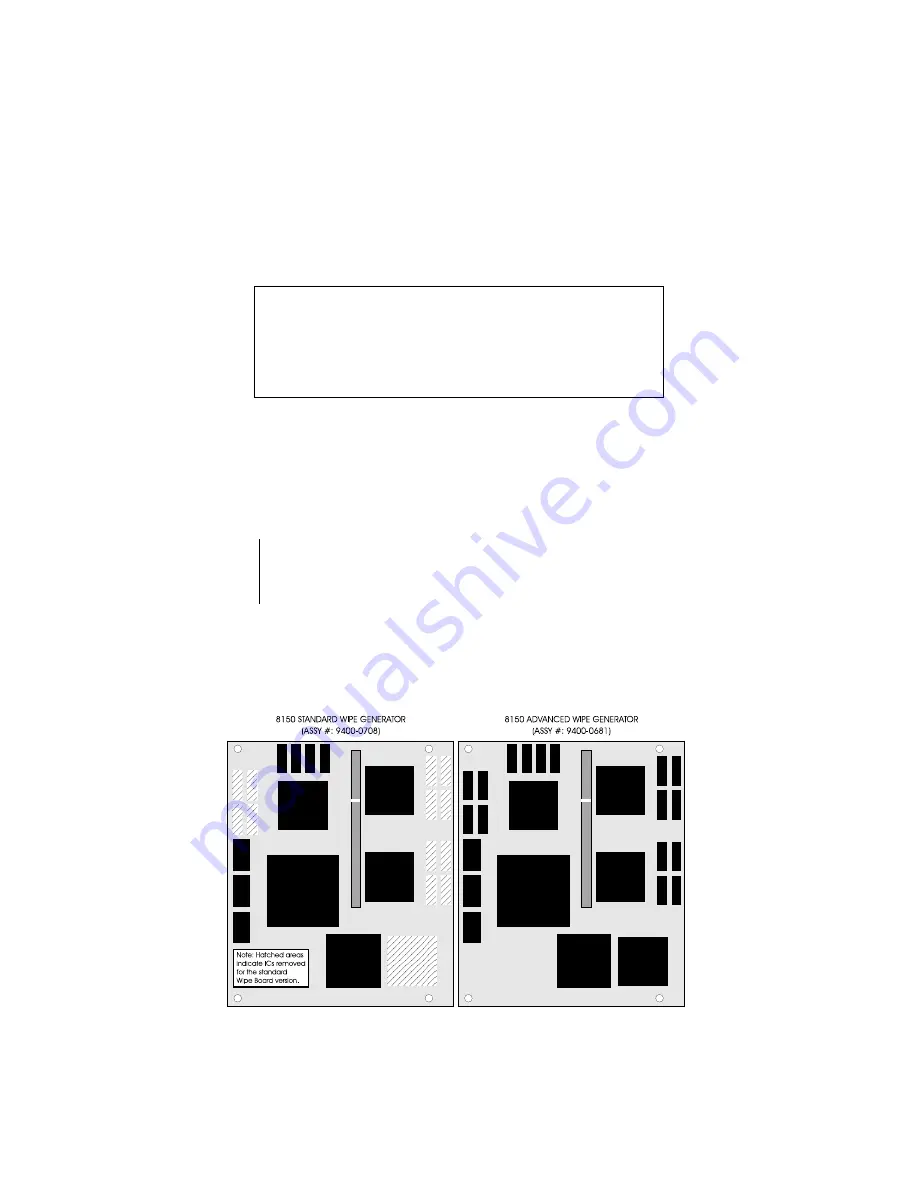
Standard or Advanced Wipe Generator
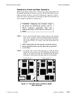
Before proceeding, ensure that you have the correct sub-board; the
Standard Wipe Generator board is Accom P/N 9400-0708; the Advanced
Wipe Generator board is Accom P/N 9400-0681. Figure 3-11, below,
shows the major components on both Wipe Generator sub-boards and
their assembly numbers for identification.
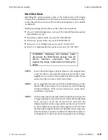
WARNING: Removing the Switcher board
disconnects the RAM battery backup. Save all
effects, timelines, personality files, and
engineering setups to disk before extracting the
board.
STEP 1:
Power down the 8150 Signal Chassis. Remove the integral
front cover/air filter to access the 8150 Switcher board. Use
the Accom supplied tool to extract the Switcher board from
the chassis and lay it on a clean, static free, grounded work
surface.
NOTE: Seating the sub-board requires moderate pressure.
Ensure that the Switcher board is sufficiently supported so
as not to flex.
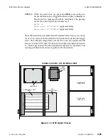
STEP 2:
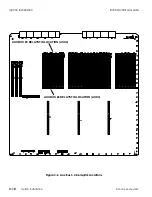
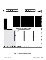
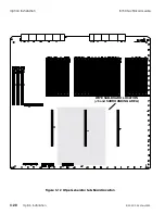
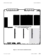
See Figure 3-12, on the following page, to locate the Wipe
Generator sub-board (J6 and surrounding shaded area).
Remove the screws securing the installed Wipe Generator
sub-board to the Main board, then remove the sub-board.
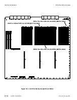
Figure 3-11 Standard (Left) & Advanced (Right)
Wipe Generator
8150 Technical Guide
Option Installation
9100-0212-04 - May 2000
Option Installation
3-19
Summary of Contents for ASWR8150
Page 12: ...Table of Contents 8150 Technical Guide X Contents 9100 0212 04 May 2000...
Page 39: ......
Page 80: ...Control Panel Connector Detail 8150 Technical Guide 2 40 Installation 9100 0212 04 May 2000...
Page 109: ...Option Installation 8150 Technical Guide 3 30 Option Installation 9100 0212 04 May 2000...
Page 236: ...8150 Partial Parts List 8150 Technical Guide A 6 Appendix 9100 0212 04 May 2000...

