


23
7 - INSTALLAZIONE E MESSA IN SERVIZIO
7 - INSTALLATION AND START UP
7.8 COLLEGAMENTI IDRAULICI SEZIONE SBFR
7.8 SBFR SECTION HYDRAULIC CONNECTIONS
▪
Le operazioni di installazione e collegamento delle tubazioni
sono operazioni che possono compromettere il buon
funzionamento dell'impianto o, peggio, causare danni
irreversibili alla macchina. Queste operazioni sono da
effettuarsi da personale specializzato.
▪
L'eventuale sezione con batteria ad acqua è fornita di
attacchi "maschio" con filettatura gas.
▪
Le operazioni di serraggio vanno effettuate con cautela per
evitare danneggiamenti dei collettori in rame della batteria.
▪
Il percorso dei tubi deve essere studiato in modo da non
creare ostacoli in caso di estrazione della batteria dell'unità.
▪
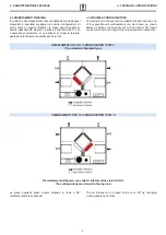
Entrata e uscita acqua devono essere tali da consentire
lo scambio termico in controcorrente: seguire quindi le
indicazioni delle targhette ENTRATA ACQUA e USCITA
ACQUA.
▪
Prevedere una valvola di sfiato in alto ed una di scarico in
basso.
▪
Staffare adeguatamente i tubi all'esterno della sezione per
evitare di scaricarne il peso sulla batteria.
▪
A collegamento effettuato spingere bene la guarnizione
esterna in gomma contro il pannello per evitare trafilamenti
d'aria.
▪
La coibentazione deve giungere a filo pannello per evitare
pericolo di condensazioni.
▪
Prevedere dispositivo antigelo.
▪
Prevedere valvole di intercettazione per isolare la batteria
dal resto dei circuito in caso di manutenzione straordinaria.
▪
Nel caso di installazione in zone con climi particolarmente
freddi, svuotare l'impianto in previsione di lunghi periodi di
ferma dell'impianto.
▪
The installation and connection operations of the pipes are
operations that can compromise the good functioning of the
plant or worse, cause irreversible damage to the machine.
These operations must only be performed by specialised
staff.
▪
The section with water coil is supplied with "male"
connections with gas threading.
▪
Tightening must be performed carefully to prevent damage
to the copper collectors in the coil.
▪
The route of the pipes must be studied in a way not to create
obstacles if the unit coil is extracted.
▪
Water inlet/outlet must be such to allow countercurrent heat
exchange: follow the indications of the WATER INLET and
WATER OUTLET plates.
▪
Envision a high vent valve and a low discharge valve.
▪
Clamp the pipes adequately to the outside of the section to
prevent the weight being unloaded onto the coil.
▪
When connection has been made, push the external gasket
well against the panel to prevent seepage of air.
▪
Insulation must be flush to the panel in order to prevent the
danger of condensation.
▪
Envision anti-freeze device.
▪
Envision on-off valves to isolate the coil from the rest of the
circuit in the case of extraordinary maintenance.
▪
In the case of installation in zones with particularly cold
climates, empty the plant for long standstill periods.
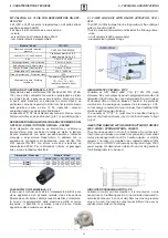
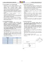
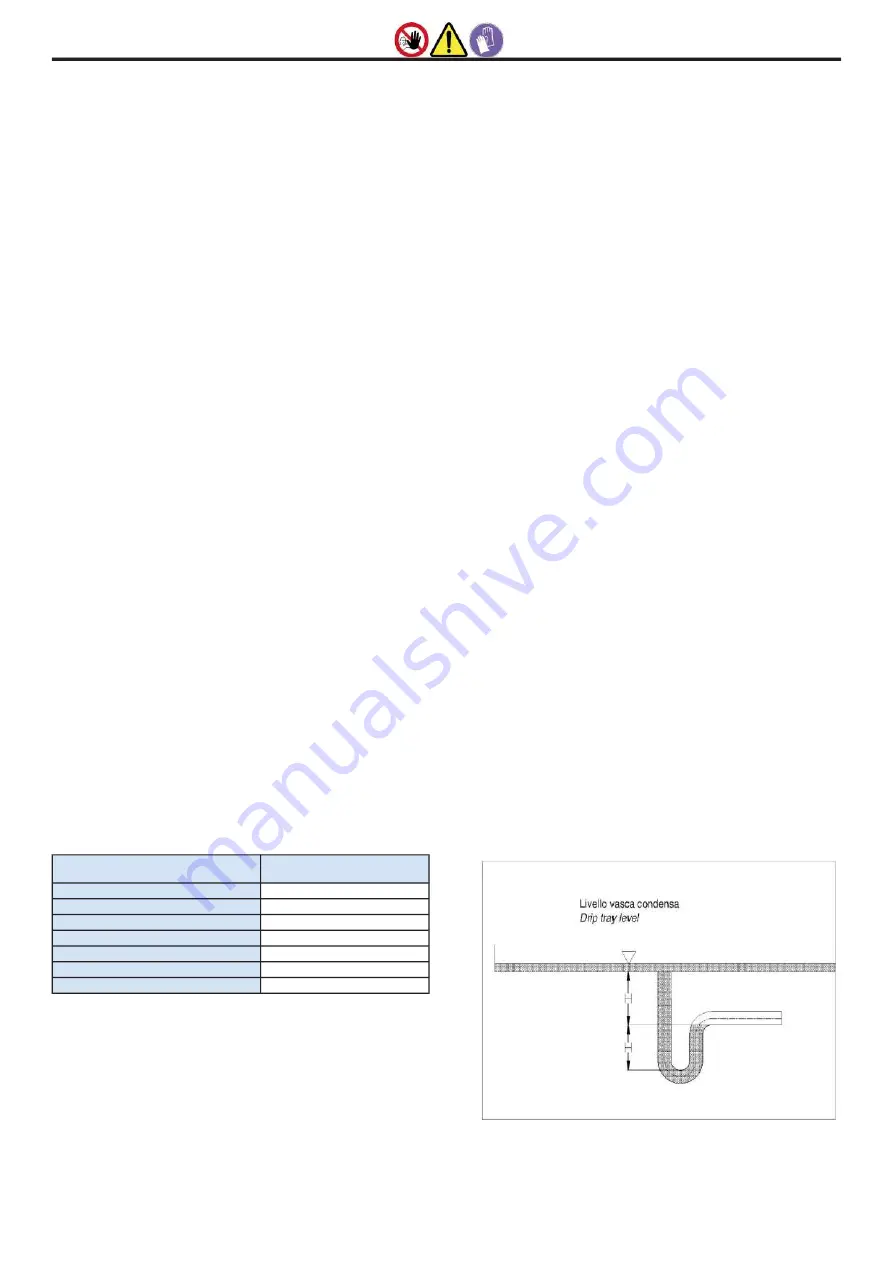
7.8.1 COLLEGAMENTO SCARICO CONDENSA SEZIONE
SBFR
7.8.1 CONNECTION OF THE SBFR SECTION CONDENSATE
DRAIN
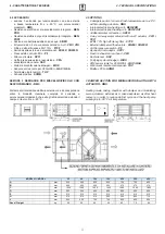
▪
La vasca di raccolta condensa in acciaio inox e provvista di
scarico con diam. esterno 22 mm (fig. 7).
▪
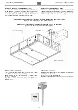
Il sistema di scarico deve prevedere un adeguato sifone per
prevenire l'infiltrazione di odori o insetti: seguire le stesse
indicazioni costruttive alla pagina precedente.
▪
Il sifone deve infine essere dotato di tappo per la pulizia
nella parte bassa o deve comunque permettere un veloce
smontaggio per la pulizia.
▪
Il percorso del tubo di scarico condensa deve avere sempre
un pendenza verso l’esterno.
▪
Assicurarsi che il tubo per il deflusso della condensa non
solleciti l’attacco di scarico.
▪
The stainless steel condensate drip tray has a drain with
external diameter of 22 mm (fig. 7).
▪
The drain system must have a suitable siphon in order to
prevent the infiltration of odours or insects: follow the same
drawings of the previous page.
▪
The siphon must finally have a cap for cleaning the lower
part or must however allow quick disassembly for cleaning.
▪
The route of the condensate drain pipe must always slope
towards the outside.
▪
Make sure that the condensate flow pipe does not stress the
drain connection.
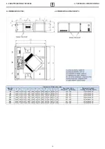
Modello /
Model
H (mm)
35
60
60
60
100
80
150
80
230
80
320
80
450
80
fig. 7
pag.24 - Manuale di installazione, Uso e Manutenzione -
Installation, Use and Maintenance Manual


