Hardware Installation
2-3
6. Connect the Ethernet Cable
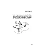
– The access point can be
wired to a 10/100 Mbps Ethernet through a network device
such as a hub or a switch. Connect your network to the RJ-45
port on the back panel with category 3, 4, or 5 UTP Ethernet
cable. When the access point and the connected device are
powered on, the Ethernet Link LED should light indicating a
valid network connection.
Note:
The RJ-45 port on the access point uses an MDI pin
configuration, so you must use straight-through cable for
network connections to hubs or switches that only have
MDI-X ports, and crossover cable for network connections to
PCs, servers or other end nodes that only have MDI ports.
However, if the device to which you are connecting supports
auto-MDI/MDI-X operation, you can use either
straight-through or crossover cable.
7. Position the Antennas
– Each antenna emits a radiation
pattern that is a toroidal sphere (doughnut shaped), with the
coverage extending most in the direction perpendicular to the
antenna. Therefore, the antennas should be oriented so that
the radio coverage pattern fills the intended horizontal space.
Also, the diversity antennas should both be positioned along
the same axes, providing the same coverage area. For
example, if the access point is mounted on a horizontal
surface, both antennas should be positioned pointing
vertically up to provide optimum coverage.
8. Connect the Console Port
– Connect the console cable
(included) to the RS-232 console port for accessing the
command-line interface. You can manage the access point
using the console port (Chapter 6), the web interface
(Chapter 5), or SNMP management software such as HP’s
OpenView.
Summary of Contents for WA6102X
Page 27: ...Hardware Installation 2 4 ...


