background image


3002 MICROSCOPE SERIES 


ACCU-SCOPE

®


73 Mall Drive, 

Commack, NY  11725  •  631-864-1000  •  www.accu-scope.com 

21


TROUBLESHOOTING 

(continued)


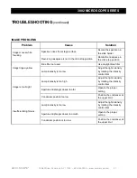
IMAGE PROBLEMS 

Problem 

Cause 

Solution 

Image moves while 
focusing 

Specimen rises from stage surface 

Secure the specimen in 
the slide holder 

Revolving nosepiece is not in the click-stop position 

Rotate the nosepiece in 
the click-stop position 

Image tinged yellow 

Blue filter not used 

Use daylight blue filter 

Lamp intensity is too low 

Adjust the light intensity 
by rotating the intensity 
control dial 

Image is too bright 

Lamp intensity is too high 

Adjust the light intensity 
by rotating the intensity 
control dial 

Aperture diaphragm closed too far 

Open to the proper 
setting 

Condenser position too low 

Position the condenser at 
the upper limit 

Insufficient Brightness 

Lamp intensity is too low 

Adjust the light intensity 
by rotating the intensity 
control dial 

Aperture diaphragm closed too much 

Open to the proper 
setting 

Condenser position is too low 

Position the condenser at 
the upper limit 


Summary of Contents for 3002

Page 1: ...MANUAL 73 Mall Drive Commack NY 11725 631 864 1000 P 631 543 8900 F www accu scope com info accu scope com 3002 MICROSCOPE SERIES ...

Page 2: ...5 CONTROLS DIAGRAM 6 7 ASSEMBLY DIAGRAM PROCEDURE 8 12 ADJUSMENT OPERATION BRIGHTNESS 13 PLACING THE SPECIMEN 13 FOCUSING TENSION 14 FOCUSING 14 CONDENSER 15 IRIS DIAPHRAGM 15 INTERPUPILLARY DISTANCE 16 EYEPIECE DIOPTER 16 LED LAMP SPECIFICATIONS OPERATION RECHARGING 17 TROUBLESHOOTING LED LAMP 18 TECHNICAL SPECIFICATIONS 19 TROUBLESHOOTING 20 22 MAINTENANCE 23 SERVICE 23 WARRANTY 23 ...

Page 3: ...ding eyepieces objectives or focusing assembly 2 Keep the instrument clean remove dirt and debris regularly Accumulated dirt on metal surfaces should be cleaned with a damp cloth More persistent dirt should be removed using a mild soap solution Do not use organic solvents for cleansing 3 The outer surface of the optics should be inspected and cleaned periodically using an air stream from an air bu...

Page 4: ...ed technicians in our New York facility Careful quality control procedures ensure each microscope is of the highest quality prior to shipment UNPACKING AND COMPONENTS Your microscope arrived packed in a molded Styrofoam container Do not discard the container the Styrofoam container should be retained for reshipment of your microscope if needed Avoid placing the microscope in dusty surroundings or ...

Page 5: ...www accu scope com 5 COMPONENTS DIAGRAM Iris Diaphragm Adjustment Lever Interpupillary Distance Adjustment Binocular Viewing Head Coarse Focus Adjustment Knob Eyepieces Objective Mechanical Stage Illuminator Housing On Off Switch Fine Focus Adjustment Knob ...

Page 6: ...25 631 864 1000 www accu scope com 6 CONTROLS DIAGRAMS Diopter Adjustment Ring Interpupillary Distance Adjustment Condenser Adjustment Knob Upper Limit Stage Locking Lever Variable Light Intensity Dial Coarse Focusing Knob Fine Focusing Knob ...

Page 7: ...25 631 864 1000 www accu scope com 7 CONTROLS DIAGRAMS continued Y Stage Movement Adjustment Knob X Stage Movement Adjustment Knob Fine Focusing Adjustment Knob Coarse Focusing Adjustment Knob Tension Adjustment Collar On Off Switch Iris Diaphragm Adjustment Lever ...

Page 8: ...mbly Your microscope was preassembled by our factory technicians at our New York facility prior to shipment Should you need to disassemble assemble your microscope in the future please follow the instructions outlined below When assembling the microscope make sure that all parts are free of dust and dirt and avoid scratching any parts or touching glass surfaces Eyepieces Objectives Power Cord Bino...

Page 9: ...ng Head Loosen the lock screw and carefully insert the binocular viewing head into the main body Rotate the head so it is facing forward then tighten the lock screw as shown in Fig 1 2 Installing the Eyepieces Remove the protective caps from the eyepiece tubes Insert the eyepieces into the eyepiece tubes as shown in Fig 3 4 Fig 1 Fig 4 Fig 2 Fig 3 ...

Page 10: ...al stage reaches its lowest limit position Screw the 4 objective into the nosepiece from the left or the right side then rotate the nosepiece clockwise and mount other objectives by the sequence of low to high magnification as shown in Fig 6 Installing the Glass Filter Swing out the condenser holder Fig 7 and insert the filter into the holder Swing the holder back in place Fig 5 Fig 6 Fig 7 ...

Page 11: ...sert the female end of the power cord plug securely into the power cord socket on the back of the microscope Fig 9 Connect the other end into a 110v 220v outlet Fig 10 Replacing the Fuse Before replacing the fuse make sure the switch is off O and unplug the power cord from outlet Using a flat head screwdriver remove the fuse holder Fig 9 and unscrew the old fuse and insert the new fuse Replace the...

Page 12: ...TOUCH the halogen bulb with bare hands as it may shorten the lamp life Wrap it with gauze a soft piece of lint free cloth or handle with cotton gloves Ensure the power switch is off and the lamp is cooled before handling Pull out and remove the illuminator housing as shown in Fig 11 and as shown in Fig 12 insert the pin side of the lamp completely into the lamp socket Reinstall the illuminator hou...

Page 13: ...front of the microscope base to increase the brightness turn it toward the back of the microscope base to decrease the brightness Placing the Specimen Place the specimen on the center of the stage and use the slide holder to gently secure the slide Fig 15 Rotate the X and Y adjustment knobs of the mechanical stage to position the specimen for viewing Use caution when changing objectives do not all...

Page 14: ... obtain sharp images with both eyes since individual eyes vary especially for those wearing glasses any eyesight variation can be corrected in the following manner set both diopter collars to 0 Using your left eye only and the 10X objective focus your specimen by adjusting the coarse adjustment knob Fig 16 When the image is in view refine the image to its sharpest focus by turning the fine adjustm...

Page 15: ... the light axes of the objective are factory adjusted DO NOT attempt to re adjust Adjusting the Iris Diaphragm Move the iris diaphragm lever Fig 18 left or right to adjust the aperture size The iris diaphragm is designed to adjust the aperture size not to adjust brightness Generally reducing the diaphragm opening to 70 80 of the N A value of the respective objective will provide an image of accept...

Page 16: ...erator fatigue and will disrupt the objective parfocality Where on the eyepiece tube lines up then that is the number for the interpupillary distance IPD Range 52 75mm Fig 19 Remember your interpupillary for future operation Adjusting the Eyepiece Diopter Using the 10x objective and your right eye only observe your specimen through the right eyepiece and bring it into focus Observe the specimen wi...

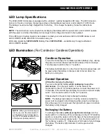
Page 17: ...on The battery light indicator on the front of the microscope base will be green when the battery is charged and turns red when the battery is running low Corded Operation While Recharging the Battery You can recharge the battery while continuing to use the microscope Turn the main switch on the base of the microscope to the off O middle position connect the power cord to the base of the microscop...

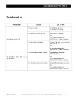
Page 18: ...your local authorized ACCU SCOPE dealer for service The LED lamp is damaged Change the LED lamp assembly CAT 02 3259 OR call your local authorized ACCU SCOPE dealer for service The brightness of the LED lamp is not adequate The rechargeable battery is aging Replace the battery pack CAT 02 1060 OR call your local authorized ACCU SCOPE dealer for service The charging circuit is not working Replace t...

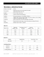
Page 19: ...g system the minimum division of fine focusing 0 002mm focus adjustment range 23mm Condenser Abbe Condenser NA 1 25 with Iris Diaphragm Filter Holder Stage Double Plate Mechanical Stage 140mm 140mm Movement Range 75 50mm Illumination Halogen Lamp 6V 20W or 1 watt LED Objectives Magnification Numerical Aperture NA Thickness of cover slip mm Working Distance mm Type 4X 0 10 0 17 37 5 Dry 10X 0 25 0 ...

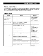
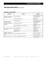
Page 20: ...osepiece to click stop position by swinging the objective correctly into the optical path Dirt or dust on the view field Dirt or dust on the lens eyepiece condenser objective collector lens or specimen Clean the lens Poor image quality No coverglass attached to the slide Attach a 0 17mm coverglass Coverglass is too thick or thin Use a coverglass of the appropriate thickness 0 17mm Slide may be ups...

Page 21: ...Use daylight blue filter Lamp intensity is too low Adjust the light intensity by rotating the intensity control dial Image is too bright Lamp intensity is too high Adjust the light intensity by rotating the intensity control dial Aperture diaphragm closed too far Open to the proper setting Condenser position too low Position the condenser at the upper limit Insufficient Brightness Lamp intensity i...

Page 22: ...from low power objective Slide upside down Turn the slide over so the coverglass faces up Cover glass is too thick Use a 0 17mm coverglass Diopter adjustment is not set properly Readjust the diopter settings Lamp does not light when switched on No electrical power Check power cord connection Lamp burnt out Replace lamp Fuse blown out Replace fuse Slippage of focus when using the coarse focusing kn...

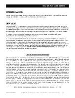
Page 23: ...orkmanship for a period of five years from the date of invoice to the original end user purchaser The LED lamp is warranted for a period of two years from the date of invoice to the original end user purchaser This warranty does not cover damage caused in transit misuse neglect abuse or damage resulting from improper servicing or modification by other then ACCU SCOPE approved service personnel Thi...

Reviews: