7-4
Troubleshooting
AXIOM™ 400 Product Manual
Accu-Sort Systems, inc.
07-AXIOM400-Troubleshooting_R10.doc
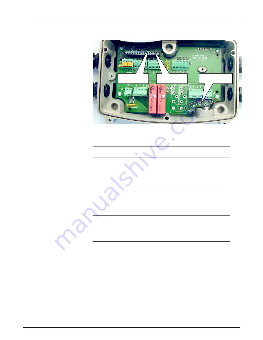
Wiring Base Status Indicator LEDs
Figure 7-2:
Wiring Base Status LED Locations
Table 7-4:
Wiring Base Status LED Descriptions
Status
LEDs
Location / Definition
Polarity
Near input power TB. Also referred to as Power LED.
RED
if power polarity is reversed.
GREEN
if power polarity is correct.
OFF indicates no power.
DO NOT install the Axiom scan head if this LED is
RED
.
Tach
On outside edge of circuit board, behind scan head connector.
If tachometer wheel is slowly rotated, the Tach LED will flash
GREEN
.
(See Verify Tachometer Operation procedure in Chapter 6.)
Trigger
On outside edge of circuit board, behind scan head connector.
When the trigger photoeye is blocked, the Trigger LED will light
GREEN
.
(See Verify Photoeye Operation procedure in Chapter 6.)
Polarity LED
Tach LED
Trigger LED
Summary of Contents for AXIOM 400
Page 1: ...AXIOM 400 Bar Code Scanning Solutions Product Manual...
Page 96: ...8 8 Service AXIOM 400 Product Manual Accu Sort Systems inc 08 AXIOM400 Service_R10 doc Notes...
Page 104: ...B 2 Read Charts AXIOM 400 Product Manual Accu Sort Systems inc A2 AXIOM400 ReadCharts_R10 doc...
Page 105: ...AXIOM 400 Product Manual Read Charts B 3 A2 AXIOM400 ReadCharts_R10 doc Accu Sort Systems inc...
Page 106: ...B 4 Read Charts AXIOM 400 Product Manual Accu Sort Systems inc A2 AXIOM400 ReadCharts_R10 doc...
Page 107: ...AXIOM 400 Product Manual Read Charts B 5 A2 AXIOM400 ReadCharts_R10 doc Accu Sort Systems inc...


