background image


  Accu-Sort

®

 Systems, inc.   


511 School House Road 


Telford, PA  18969  U.S.A. 

  1-800-BAR-CODE 

  1-(215)-723-0981 


This copy expires 7 days after: 8/25/06 
unless stamped "CONTROLLED 
COPY" in red 

Issued: 07/06/05 
Revised:  


 TP-ENM-704


 Rev. 


Page 19 of 22 

Annotations to this document are acceptable only if done in RED pen and initialed by a 

representative of the department responsible for the creation and maintenance of the document 

RFR-02 READER TEST PROCEDURE 


______________________________________________________________________________ 

THIS IS A CONTROLLED COPY ONLY IF STAMPED “CONTROLLED COPY” IN RED. 

©

Accu-Sort Systems, inc. 


7.60 

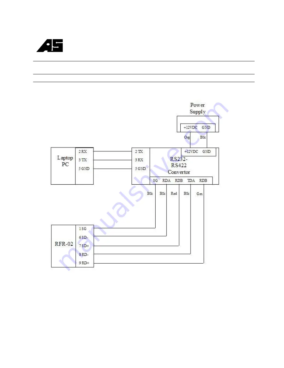
Plug the cable connected to the RS422 side of the converter to the RFR-02’s network port. 


7.61 

Power on RFR-02. 

 
7.62 

Type “R99” a few times.  Procomm should display VALID READS: 100/100, this checks 
the communication for the RS422 section of the Network port. Record as passed. 

Summary of Contents for RFR-02

Page 1: ...65 12 VDC Power and 1000053245 10 30 VDC Power 2 0 SCOPE This document applies to any of the above items that have the potential of being shipped to a customer in order to fulfill a sample request or...

Page 2: ...FID Tag RFID Tag 7 Test Stand Input Test Wiring Harness Output Test Wiring Harness Serial Cable 9pin Male 9pin Female w Pins 2 3 and 5 Straight B B Electronics Model 485PTBR RS232 RS422 Converter 7 0...

Page 3: ...cation of file may vary on from shown 7 9 2 Select R02STD05 HEX or current released version of firmware 7 9 3 Click on Download turn on power after a one second delay The network LED RED should be fla...

Page 4: ...NM 704 Rev A Page 4 of 22 Annotations to this document are acceptable only if done in RED pen and initialed by a representative of the department responsible for the creation and maintenance of the do...

Page 5: ...______________________________________________________________________ THIS IS A CONTROLLED COPY ONLY IF STAMPED CONTROLLED COPY IN RED Accu Sort Systems inc 7 12 Setting Amplitude On the Spectrum Ana...

Page 6: ...the Spectrum Analyzer 7 14 1 Press SPAN 7 14 2 Press 5 0 0 then KHz Span is now set 7 15 Plug the BNC cable to antenna input 1 7 16 Verify that the amplitude is 22 dBm tolerance 1 5 dB 7 17 Press TRA...

Page 7: ...ion and maintenance of the document RFR 02 READER TEST PROCEDURE ______________________________________________________________________________ THIS IS A CONTROLLED COPY ONLY IF STAMPED CONTROLLED COP...

Page 8: ...__________ THIS IS A CONTROLLED COPY ONLY IF STAMPED CONTROLLED COPY IN RED Accu Sort Systems inc 7 28 Checking Antenna 2 Port 7 28 1 If Antenna LED is lit on the RFR 02 antenna 1 is selected 7 28 2 C...

Page 9: ...cument are acceptable only if done in RED pen and initialed by a representative of the department responsible for the creation and maintenance of the document RFR 02 READER TEST PROCEDURE ____________...

Page 10: ...document RFR 02 READER TEST PROCEDURE ______________________________________________________________________________ THIS IS A CONTROLLED COPY ONLY IF STAMPED CONTROLLED COPY IN RED Accu Sort Systems...

Page 11: ...T PROCEDURE ______________________________________________________________________________ THIS IS A CONTROLLED COPY ONLY IF STAMPED CONTROLLED COPY IN RED Accu Sort Systems inc 7 30 Type R299 to get...

Page 12: ...THIS IS A CONTROLLED COPY ONLY IF STAMPED CONTROLLED COPY IN RED Accu Sort Systems inc 7 34 2 Remove cable from antenna 2 and plug into antenna 1 of the RFR 02 7 34 3 Use the 7 spacer and reference ta...

Page 13: ...rtment responsible for the creation and maintenance of the document RFR 02 READER TEST PROCEDURE ______________________________________________________________________________ THIS IS A CONTROLLED COP...

Page 14: ...IF STAMPED CONTROLLED COPY IN RED Accu Sort Systems inc 7 39 1 On the variable power supply the cable from the fixed voltage section 6VDC should be connected to the output port on the reader 7 39 2 LE...

Page 15: ...S IS A CONTROLLED COPY ONLY IF STAMPED CONTROLLED COPY IN RED Accu Sort Systems inc 7 41 Measure the voltage between pins 2 and 4 of the test header voltage should fall between 11 30 and 11 40 VDC 7 4...

Page 16: ...nnected between the yellow wire and the power supply should light Note the blue LED on the lid should not light 7 45 Connect Blue jumper wire between common of power supply and pin 5 of the test heade...

Page 17: ...eation and maintenance of the document RFR 02 READER TEST PROCEDURE ______________________________________________________________________________ THIS IS A CONTROLLED COPY ONLY IF STAMPED CONTROLLED...

Page 18: ...______________________________________________________________ THIS IS A CONTROLLED COPY ONLY IF STAMPED CONTROLLED COPY IN RED Accu Sort Systems inc 7 55 Power RFR 02 on 7 56 Type R99 on Procomm afte...

Page 19: ...epartment responsible for the creation and maintenance of the document RFR 02 READER TEST PROCEDURE ______________________________________________________________________________ THIS IS A CONTROLLED...

Page 20: ...EXIT This sets the RFR 02 s parameters back to the default values 7 64 Power down RFR 02 7 65 Disconnect all cables from RFR 02 7 66 Attach Lid to RFR 02 making sure that the metal gasket is properly...

Page 21: ...ment RFR 02 READER TEST PROCEDURE ______________________________________________________________________________ THIS IS A CONTROLLED COPY ONLY IF STAMPED CONTROLLED COPY IN RED Accu Sort Systems inc...

Page 22: ...is setup correctly per steps 7 12 through 7 14 7 73 7 Power on RFR 02 and record max amplitude of the 13 56 Mhz signal tolerance is 22 dBm 1 5 dB This is for antenna 1 Record Max amplitude 7 73 8 For...

Reviews: