


M 0492
-
14
I
E
a
b
h
I
E
I
E
GB
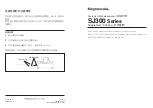
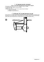
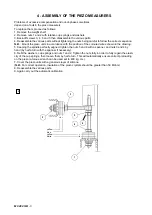
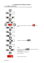
9 - WHEEL MEASUREMENT AND SETTING ON THE WHEEL
BALANCER
The need for ever more accurate calibration and the use of the ALU buttonsmakes it important to define
how the rims must be measured and how the wheel balancer interprets the data set. Hence we indicate
how the set dimensions are automatically changed in order to obtain the distances of the correction planes
which are defined as through-planes for the centres of gravity of the correction weights.
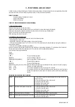
Let us consider a typical rim: The measurement “
l
” given as rim width by the manufacturer differs from
the distance measured between the correction planes for the rim thickness and the physical dimensions
of the counterweight whose centre of gravity is at distance “h” from the resting point on the edge of the
rim. The wheel balancer automatically corrects the set measurement by adding 2 x h = 6 mm to the
measurement. The measurement “b” made with the gauge is normally more accurate even if very
similar to the measurement “
l
” known by the user. The two measurements differ only by the thickness
of the plate, usually about 2 mm per side. This minimal difference allows obtaining accurate calibration
by indifferently setting the inside width “
l
” or the outside width “b” of the rim. It is a good rule to add 1/4
inch to the value given by the rim manufacturer. As regards the ALU functions, the machine performs the
following approximations in addition to systematic correction of the centre of gravity of the counterweight
as seen above.
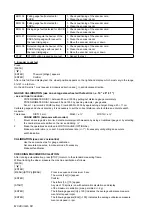
NOTE
: I = INSIDE
E = OUTSIDE
a = a ¾”
b = b preset - 1 ½”
dI = d preset - 1”
dE = d preset - 1”
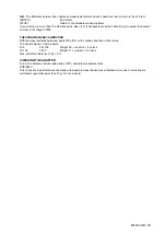
a = a ¾”
b = distance of adapter surface - ½” - a
dI = d preset - 1”
dE = d preset - 2
½”
a = a preset
b = distance of adapter surface - ½” - a
dI = d preset
dE = d preset - 2
½”
a = a preset
b = b preset - ¾”
dI = d preset
dE = d preset - 1”
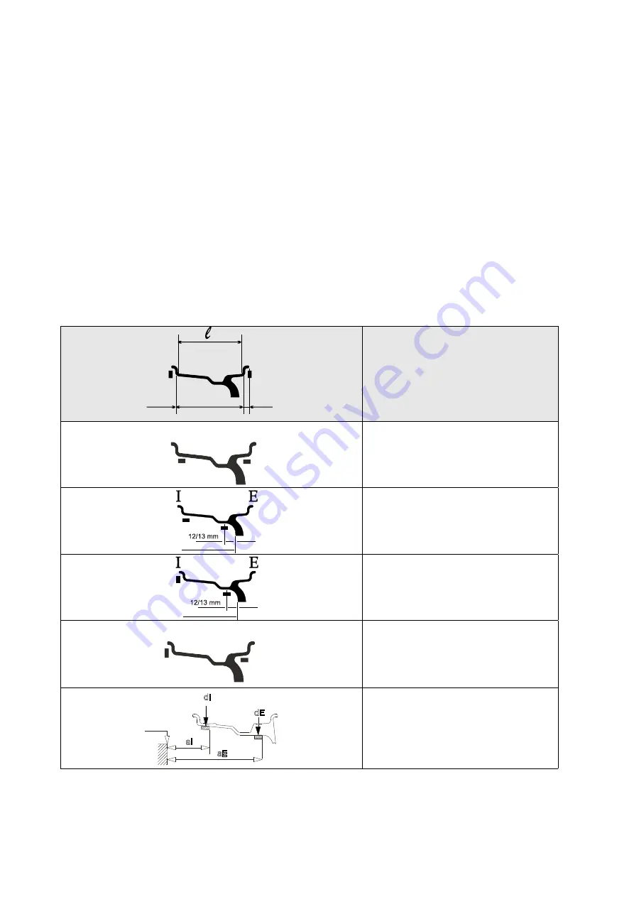
a = aI preset - 8 mm
b = aE - aI
dI = d preset
dE = d preset - 1”
resting surface
resting surface
0 gauge
Summary of Contents for 1250
Page 1: ...SERVICE MANUAL MODELS 1250 1450 1550 1650 1850...
Page 2: ......
Page 3: ...Model 1250 Wheel Balancer...
Page 5: ...M 0495 2 GB...
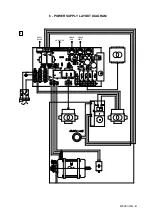
Page 9: ...M 0495 6 3 GB 5 POWER SUPPLY LAYOUT DIAGRAM 230 V connection...
Page 10: ...M 0495 7 4 GB 6 REPLACING THE POWER BOARD check voltage...
Page 14: ......
Page 15: ...Model 1450 Wheel Balancer...
Page 17: ...M 0492 2 GB...
Page 30: ......
Page 31: ...Model 1550 Wheel Balancer...
Page 33: ...M 0493 2 GB...
Page 40: ...M 0493 9 5 GB 6 POWER SUPPLY LAYOUT DIAGRAM...
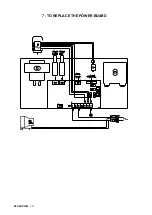
Page 41: ...M 0493 10 6 GB 7 TO REPLACE POWER BOARD...
Page 46: ......
Page 47: ...Model 1650 Vibration Control Diagnostic System...
Page 49: ...M 0494 2 GB...
Page 55: ...M 0494 8 5 GB 7 POWER SUPPLY LAYOUT DIAGRAM...
Page 56: ...M 0494 9 6 GB 8 TO REPLACE POWER BOARD...
Page 62: ......
Page 63: ...Model 1850 Wheel Balancer...
Page 65: ...M 0496 GB 2...
Page 76: ...SERVICE MANUAL MODELS 1250 1450 1550 1650 1850...