


6
4
5
3
2
1
M 0496 GB
-
5
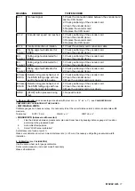
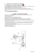
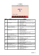
3.3 - CALIBRATION OF THE DIAMETER POTENTIOMETER
- After
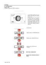
CALIBRATION OF THE DISTANCE POTENTIOMETER
press
- The wording
[dlA]
appears on the left display, a number which varies when the gauge is turned appears on the right
displayand represents a reference for calibrating the potentiometer.
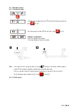
- Unscrew the diameter potentiometer from the gauge rod releasing the fixing screw.
- Slightly pull out the gauge rod and rest its stop on the machine shaft in external position near the base.
- Turn the potentiometer shaft until a number between 50 and 100 is read, then place it back in its correct working
position.
- Lock the potentiometer with the relative screw.
- Carry out the
DIAMETER GAUGE CALIBRATION
.
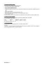
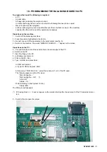
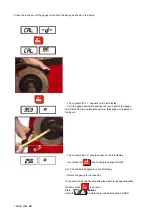
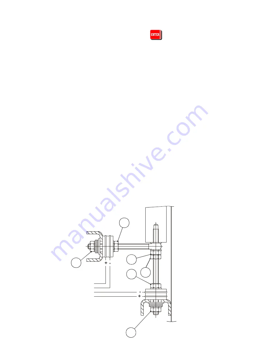
4 - ASSEMBLY OF THE PIEZO MEASURERS
Problems of excessive compensation and out-of-phase sometimes depend on a fault in the piezo measurers.
To replace them, proceed as follows:
1. Remove the weight shelf.
2. Remove nuts 1 and 2 with relative cup springs and washers.
3. Back-off screws 3, 4, 6 and 5 then disassemble the various parts.
4. Reassemble the various parts without tightening the nuts being careful to follow the correct sequence.
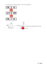
N.B.
:
Mount the piezo units in accordance with the position of the coloured wires shown in the drawing.
5. Keeping the spindle perfectly aligned, tighten the nuts 5 and 6 with a spanner, and nuts 3 and 4 by hand (by half a
turn with the spanner if necessary).
6. Refit the washers, cup springs and nuts 1 and 2. Tighten the nuts fully in order to fully regain the elasticity of the
cup springs, then loosen them by half a turn. This will automatically ensure correct preloading on the piezo (a
torque wrench can be used set to 400 kg. cm.).
7. Cover the piezo units with a generous layer of silicone.(
N.B.:
For correct operation, insulation of the piezo
crystals should be greater than 50 Mohm
).
8. Reassemble the various parts.
9. Again carry out the automatic calibration.
yellow
blue
yellow
white
Summary of Contents for 1250
Page 1: ...SERVICE MANUAL MODELS 1250 1450 1550 1650 1850...
Page 2: ......
Page 3: ...Model 1250 Wheel Balancer...
Page 5: ...M 0495 2 GB...
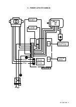
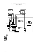
Page 9: ...M 0495 6 3 GB 5 POWER SUPPLY LAYOUT DIAGRAM 230 V connection...
Page 10: ...M 0495 7 4 GB 6 REPLACING THE POWER BOARD check voltage...
Page 14: ......
Page 15: ...Model 1450 Wheel Balancer...
Page 17: ...M 0492 2 GB...
Page 30: ......
Page 31: ...Model 1550 Wheel Balancer...
Page 33: ...M 0493 2 GB...
Page 40: ...M 0493 9 5 GB 6 POWER SUPPLY LAYOUT DIAGRAM...
Page 41: ...M 0493 10 6 GB 7 TO REPLACE POWER BOARD...
Page 46: ......
Page 47: ...Model 1650 Vibration Control Diagnostic System...
Page 49: ...M 0494 2 GB...
Page 55: ...M 0494 8 5 GB 7 POWER SUPPLY LAYOUT DIAGRAM...
Page 56: ...M 0494 9 6 GB 8 TO REPLACE POWER BOARD...
Page 62: ......
Page 63: ...Model 1850 Wheel Balancer...
Page 65: ...M 0496 GB 2...
Page 76: ...SERVICE MANUAL MODELS 1250 1450 1550 1650 1850...