


M 0496 GB
-
10
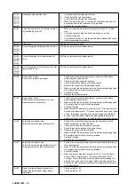
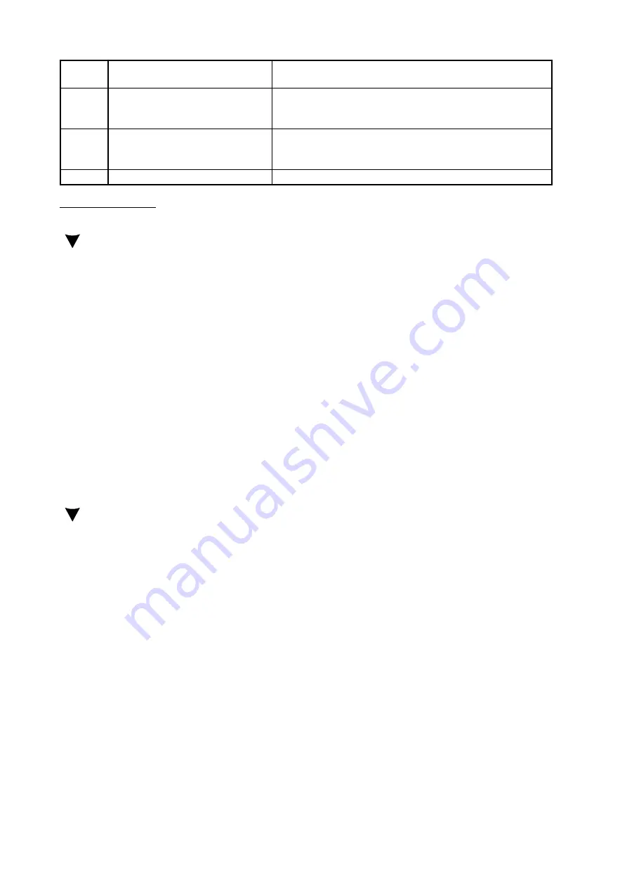
ERR. 36 Rising edge fault detected for ENCB. 1. Check positioning of the encoder card.
2. Clean the encoder decal.
ERR. 37 Detected irregular behaviour of the
ENCA falling edge with respect to
the reset rising edge.
1. Check positioning of the encoder card.
2. Clean the encoder decal.
3. Move the encoder card up or down.
ERR. 38 Detected irregular behaviour of the
ENCB falling edge with respect to
the reset rising edge.
1. Check positioning of the encoder card.
2. Clean the encoder decal.
3. Move the encoder card up or down.
STOP
[STOP] button pressed during test.
1. Repeat the test.
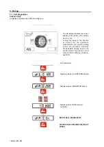
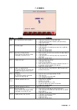
3. Encoder count test
Press:
[MENU]
[
]
[ENTER]
The word [dIAgn.] appears
[ENTER]
Confirm
After a brief LED and display test, the wheel position appears on the right-hand display, which must vary in the range
0%127 in a full turn.
On the LED matrix
↑
must appear in clockwise direction and
↓
in anticlockwise direction.
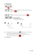
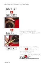
GAUGE CALIBRATION
(use an average size wheel with steel rim i,.e. 14” x 6” ± 1”) - see
CALIBRATION
and
CHECKING AND CALIBRATION OF THE GAUGES
-
DIST.= between 50 and 1000 by pulling out distance gauge completely
DIA= between 50 and 1000 by opening diameter gauge wide
Calibrate gauges and check accuracy.
Tolerances:
DIST.= 5 mm
DIAM.= ± ½”
CALIBRATION
(see
CALIBRATION
)
Use the same wheel as for gauge calibration
Set accurate measures, in manual mode if necessary
Make self-calibration
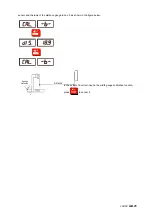
CHECKING MACHINE OSCILLATION
After running autocalibration, press [STOP] to return to the standard measuring frame.
Without locking the wheel, measure the machine oscillation as follows:
[MENU]
[
]
[ENTER]
[MENU]+[STOP]+[MENU]
Press in sequence in maximum 5 sec.
The words [Lan] [ci] appear
[ENTER]
Confirm.
The letters [t.L.] [ 10] appear
[START]
A cycle of 10 spins is run with automatic calculation and display
of the maximum oscillation (max. per/- 2 g).
[ENTER]
The following appears [Ini] [~120]: indicates the average unbalance measure
ment start speed in rpm.
[ENTER]
The following appears [End] [~100]: indicates the average unbalance measure
ment end speed in rpm.
N.B.
: The difference between the unbalance measurement start and end speed must never be more than 30 rpm.
[ENTER]
End of test.
[STOP]
Return to the standard measuring frame
If you wish to run more than 10 automatic spins, when [t.L.] [10] appears press the buttons [+]/[-] to select the desired
number in the range 5%999.
CHECKING MACHINE CALIBRATION
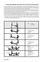
With the wheel perfectly balanced, apply 100 g first on the outside and then on the inside.
The wheel balancer must measure:
FI=0
FE=100
Weight F.E. = position = 6 o’clock
FI=100
FE=0
Weight F.I. = position = 6 o’clock
Max. permitted tolerance 100 g = 5%.
Summary of Contents for 1250
Page 1: ...SERVICE MANUAL MODELS 1250 1450 1550 1650 1850...
Page 2: ......
Page 3: ...Model 1250 Wheel Balancer...
Page 5: ...M 0495 2 GB...
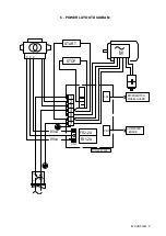
Page 9: ...M 0495 6 3 GB 5 POWER SUPPLY LAYOUT DIAGRAM 230 V connection...
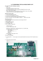
Page 10: ...M 0495 7 4 GB 6 REPLACING THE POWER BOARD check voltage...
Page 14: ......
Page 15: ...Model 1450 Wheel Balancer...
Page 17: ...M 0492 2 GB...
Page 30: ......
Page 31: ...Model 1550 Wheel Balancer...
Page 33: ...M 0493 2 GB...
Page 40: ...M 0493 9 5 GB 6 POWER SUPPLY LAYOUT DIAGRAM...
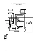
Page 41: ...M 0493 10 6 GB 7 TO REPLACE POWER BOARD...
Page 46: ......
Page 47: ...Model 1650 Vibration Control Diagnostic System...
Page 49: ...M 0494 2 GB...
Page 55: ...M 0494 8 5 GB 7 POWER SUPPLY LAYOUT DIAGRAM...
Page 56: ...M 0494 9 6 GB 8 TO REPLACE POWER BOARD...
Page 62: ......
Page 63: ...Model 1850 Wheel Balancer...
Page 65: ...M 0496 GB 2...
Page 76: ...SERVICE MANUAL MODELS 1250 1450 1550 1650 1850...