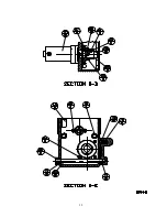
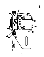
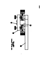
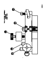
background image

35 

LIMITED WARRANTY


Accu Industries, Inc. ("Seller") provides a one year limited warranty on parts and labor on all 

goods manufactured by it, including this product.  The sole and exclusive warranty which Seller 
makes with respect to this product and all parts and accessories thereto which are sold by Seller is a 
warranty limited to defects in material or workmanship for a period of one year form the date of 
original purchase by Buyer from Seller.  For purposes of the commencement of the one-year warranty 
period, the term "Buyer" shall not include wholesalers, retailers or others who buy this product for 
resale to end users.  However, in no event shall the warranty extend beyond two years from the 
original sale (invoice date) of this product by Seller to anyone. 
             This warranty applies only to this product and any parts or accessories which are attached to or 
shipped by Seller to Buyer with it.  This warranty does not apply to equipment parts or accessories 
damaged by improper and/or negligent operation or maintenance, modification, misuse, abuse, 
neglect, abrasion or corrosion, nor to any equipment, parts, or accessories which were not 
manufactured by Seller.  This warranty does not apply to any "wear out" components of this product.  
"Wear out" shall mean those components or parts which are consumed, used or experienced wear 
during the ordinary operation of this product.  This warranty shall be void if the equipment, parts, or 
accessories are dismantled, tampered with or repairs are attempted or made by anyone other than 
Seller or its authorized agent. 

             THE EXPRESS WARRANTY SET FORTH HEREIN IS IN LIEU OF ALL OTHER 
WARRANTIES, EXPRESS OR IMPLIED, INCLUDING, BUT NOT LIMITED TO, ANY 
WARRANTIES OF MERCHANTABILITY OR FITNESS FOR A PARTICULAR PURPOSE, 
AND ALL SUCH WARRANTIES ARE HEREBY DISCLAIMED AND EXCLUDED BY 
SELLER.  THERE ARE NO WARRANTIES WHICH EXTEND BEYOND THE 
DESCRIPTION ON THE FACE HEREOF. 
             

No equipment or parts or accessories shall be shipped by Buyer to Seller without first notifying 

Seller and specifying the nature of the claimed defect.  Any such equipment, parts, or accessories 
claimed to be defective must be returned, freight prepaid, to Accu Industries, Inc., 11126 Air Park 
Road, Ashland, Virginia  23005.  If inspection by Seller shows the equipment, part, or accessory to be 
defective, Seller will repair or replace the same and if the Seller elects to repair or replace the same, 
seller will return the same to Buyer, freight prepaid. 
             Buyer's sole and exclusive remedy against Seller under this Limited Warranty shall be limited 
to repair or replacement, at Seller's option, of defective equipment, parts, or accessories covered 
hereunder.  Seller's liability shall in no event exceed that expressly set forth herein, irrespective of the 
basis for any other claim, including but not limited to claim for breach of contract, breach of warranty, 
negligence, strict liability or tort, and under no circumstance shall Seller be liable for incidental or 
consequential damages. 
             Seller shall not be liable for any losses, damages, or expenses, whether direct or indirect, 
incidental or consequential, caused by or resulting from the use of defective or nonconforming 
equipment, parts, or accessories, or from delays in delivery.  Buyer and Seller agree that the venue for 
any claim or breach of warranty shall be exclusively in the Circuit or General District Courts of 
Hanover County, Virginia. 

Summary of Contents for 8944

Page 1: ... of Lathe 9 14 Operation Procedures Multi Speed Settings Inspection Drums or Rotors Flywheels 15 18 Diagrams 19 24 Parts List 25 30 Additional Diagrams 31 Warranty When ordering parts contact your local For Records and Information Distributor give Serial of your machine Date Recv __________ and the date purchased this will help in Serial ____________ expediting your order Rep Name__________ 04 97 ...

Page 2: ...is important that you Fill Out The Enclosed Warranty Card and Mail It Back to our Headquarters This is of primary importance for authorization of warranty service for proper parts shipments to match the model of your machine and for receiving future product updates and information It is also important that you Record the Model Number Serial Number and Other Vital Information Here These numbers are...

Page 3: ...Holders 1 Boring Bar with Tool Holder 1 Standard 1 Arbor 1 Arbor Nut 1 Arbor Spring 1 1 Spacer 1 Set of Alignment Washers 3 Wrenches 1 1 2 7 8 3 8 8944 MULTI SPEED BRAKE LATHE SPECIFICATIONS 115 Volt 50 60 Hertz 1 Phase 10 0 Amps Rotor Capacity 4 to 24 Maximum width of surface 4 1 2 Maximum thickness 2 1 4 Drum Capacity 6 to 28 Friction Surface Capacity 6 Flywheel Capacity 6 to 24 Friction Surface...

Page 4: ...ake lathe Its purpose aside from proper maintenance and operations is to promote safety through the use of accepted practice READ AND UNDERSTAND THE SAFETY AND OPERATING INSTRUCTIONS COMPLETELY BEFORE OPERATING THE MACHINE In order to obtain maximum life expectancy and efficiency from your brake lathe follow the operating instructions and maintenance manual carefully The specifications put forth i...

Page 5: ...the machine its accessories and workpiece 4 Grounding the Machine In the event of a malfunction or breakdown grounding provides a path of least resistance for electric current to reduce the risk of electric shock The lathe is equipped with an electric cord having an equipment grounding conductor and a grounding plug The plug must be plugged into a matching outlet that is properly installed and gro...

Page 6: ...hen using an extension cord be sure to use one heavy enough to carry the current the lathe will draw An undersized cord will cause a drop in line voltage resulting in a loss of power and overheating Table 5 1 shows the correct size to use depending on the cord length If in doubt use the next heavier gage The smaller the gage number the heavier the cord 6 Eye Safety Wear an approved safety face shi...

Page 7: ... applying power Be sure that the rotation of the spindle is correct 14 Machining Preparation Tighten all locks before operating the lathe Be sure workpiece is secured Remove adjusting keys and wrenches Be sure to check to see that all adjusting wrenches are removed from the lathe before turning the machine on 15 Check Damaged Parts Before further use of the lathe a guard or other part that is dama...

Page 8: ...d light truck drums discs and flywheels or for operations for which the machine was not intended Grounding Pin Grounding Pin Grounding Means Cover of Grounded Outlet Box Metal Screw A B C D Adapter Fig 4 1 Volts Total lenght of cord in feet Amper Rating 120 V 25 ft 50 ft 100 ft 150 ft More Not More Than Than AWG 12 16 14 12 Not ecommended Table 5 1 ...

Page 9: ...eparts In addition if the operation is complete the operator should clean the machine and work area NEVER CLEAN THE MACHINE WITH THE POWER ON 23 Replacement Parts Use only ACCU TURN replacement parts and accessories risk of injury may result if accessories other than those recommended are used USE OF PARTS OTHER THAN ACCU TURN PARTS WILL VOID THE WARRANTY 24 Misuse Do not use the machine for other...

Page 10: ... drums rotors and most flywheels the cross feed rate should be set at a slow setting Position feed rate indicator between 0 and 3 2 The middle pulleys rotate the spindle at 150 RPM s and are normally used to machine intermediate size rotors and drums that have a larger diameter than most used on passenger cars At this spindle RPM cross feed can be set at a slow to medium feed rate Position feed ra...

Page 11: ...foot pounds Mount the drum boring bar or rotor twin cutter on the machine make sure all inserts bolts and set screws are tight Machine must be securely fastened to work bench surface before operating Four mounting holes on the base are provided for this purpose Lubrication Lubricate ways by oiling felt wipers on the end of cross slide every week with SAE 10W oil or equivalent and check gear box by...

Page 12: ... had more material removed than is allowed Proper operation cannot be established if these specifications have been exceeded ACCU Industries recommends that each workpiece be checked for size before mounting on the lathe and after machining Mounting Hubless Drums or Rotors 1 Clean and check all surfaces for flatness that will come in contact with centering cones and or bell clamps to ensure solid ...

Page 13: ...k for rust burrs or chips on cones drum or rotor bell clamps spacers arbor or other mating surfaces 7 Composite hubless rotors may require optional composite rotor adapters Mounting Hubbed Drums or Rotors 1 Select the double tapered radius adapter that properly fits the inside of the large bearing race It should sit in the race similar to a bearing and move side to side in all directions easily If...

Page 14: ...ol bit slot is toward the drum with the capscrew to the top BORING BAR EXTENSION SHOULD BE KEPT TO A MINIMUM Boring bar must not be rotated upward or downward 2 For extra small diameter drums set the boring bar at an angle towards the arbor while extending the boring bar outward from the boring bar holder 3 Turn on the machine Slowly advance the boring bar in the drum and contact the point of the ...

Page 15: ...THAN MANUFACTURER S SPECIFICATIONS 4 If surface is scored locate the deepest score and turn the rotor micrometer knob until the tool bit bottoms out at the deepest point of the score zero the scale and back out the tool bit Repeat on other side If no score exists touch rotor with tool bit near outer edge and advance calibrated hand knob until full circle is scratched on rotor and O knob Back out t...

Page 16: ...y are free of rust dirt and burrs 2 Select the centering cone that fits the center hole Then select the bell clamps that fit the cones and the center machined area of the flywheel you may use one large and one small bell clamp 3 Mount the flywheel in the same manner as a hubless rotor or drum with the side to be machined facing the lathe See example on page 17 NOTE DOWEL PINS OR STUDS MUST BE REMO...

Page 17: ... because you must stop the unit and re position the tool bar for the outside lip surface You must also remove the same amount from the outside mounting surface as was removed from the lower surface failure to do this may cause incorrect clutch operation FOR INFORMATION ON SPECIAL APPLICATIONS CONTACT YOUR ACCU TURN DISTRIBUTOR OR CALL ACCU INDUSTRIES AT 804 798 8922 Sharp Tools Are Vital To Satisf...

Page 18: ...15 PROPER MOUNTING OF HUBLESS ROTOR OR DRUM ...

Page 19: ...16 PROPER MOUNTING OF HUBBED ROTOR OR DRUM ...

Page 20: ...17 PROPER MOUNTING OF FLYWHEEL ...

Page 21: ...ors to allow resurfacing of drums and rotors with sealed bearings without having to remove the bearing assembly The above illustrates a drum from a Ford Probe Examples of this type of mounting include Toyota Vans Dodge Caravan Renault Alliance and others 436271 DRIVE ASSEMBLY OPTIONAL SEALED BEARING ASSEMBLY ...

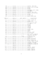
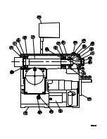
Page 22: ...ARRIER BRG 27 421643 1 GASKETS 28 411389 4 SCREW 29 420149 1 SEAL 30 433628 1 DOVE TAIL BOTTOM 31 433634 4 SCREW 32 433790 2 WEAR STRIP ASSY 33 433635 1 WAY WIPER ASSY TOP 34 433638 10 SCREW 35 433629 1 DOVE TAIL CENTER 36 433627 1 DOVE TAIL TOP 37 433630 8 SCREW SET 38 413294 8 WASHER 39 413291 8 NUT HEX 40 433639 2 SCREW TURN 41 433157 1 SCREW DRUM FEED ASSY 42 433156 1 SCREW ROTOR FEED ASSY 43 ...

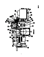
Page 23: ...433654 2 WASHER 63 421077 2 RING RETAINING EXT 64 433651 2 GEAR SPUR 70 TEETH 65 433649 2 SWITCH LIMIT 68 433908 2 COVER FEEDBOX HSING 69 434017 2 SNAP IN NYLINER 70 433909 2 HANDLE SHIFTER 71 433974 8 SCREW SET 72 1A2169 2 SPRING 73 408373 2 BALL 75 436116 2 D C FEED MOTOR 77 433735 2 TELESCOPING WAY COVER ASSY 78 433648 15 SCREW 79 433682 4 SPACER WAY COVER 80 433688 4 SCREW 81 433687 4 SCREW 82...

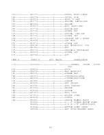
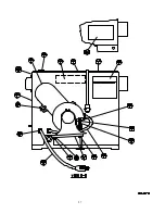
Page 24: ...34575 4 SCREW 90 433671 1 SHEAVE 91 434576 1 SHEAVE 92 433673 1 V BELT 93 436105 1 GUARD BELT 94 436109 2 SCREW 95 433685 1 LAMP 96 433674 1 FITTING VENT 97 413281 1 PLUG DRAIN 98 430866 32 OZ OIL MOBIL SYNTHETIC GEAR OIL SHC 634 99 433830 TRACE STORE AND LUBE 100 411478 1 OZ GREASE 2 101 433727 1 POWER CORD ASSY 102 433726 1 MOTOR CORD ASSY 103 433698 1 WIRE ELECTRICAL 108 433719 5 CLAMP CABLE 2 ...

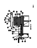
Page 25: ... VARIABLE CONTROLLER 136 436267 2 SCREW SET 137 434700 4 NUT ITEM PARTS QTY REQ D DESCRIPTION 138 433994 4 oz GREASE EXXON LIDOK OOO 139 434800 1 PLUG 140 436259 2 WAY WIPER KIT 141 436531 1 RUBBER MAT 142 436357 1 CONTROLLER KNOB 143 436358 1 CONTROLLER PLATE 178 436985 1 SHEAVE 179 433625 2 SET COLLAR 180 434581 1 ROD TENSION 181 413294 1 WASHER 182 434582 1 SPRING 183 421427 1 NUT LOCK 184 4374...

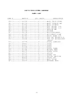
Page 26: ...307 433759 1 ADJUSTING WHEEL 308 433760 2 ADJUSTMENT SCREW 309 433761 2 CALIB WHEEL R T 311 433763 1 TOOL BIT HOLDER R H 312 434286 1 TOOL BIT HOLDER ZERO ANGLE 314 433765 2 SCREW SHOULDER 315 420212 1 SCREW 316 420211 1 SCREW 317 433766 2 SCREW 318 433767 2 SCREW THUMB 319 433768 2 WASHER WAVE 320 420772 2 SCREW DRIVE 321 433770 1 SPRING 322 433771 2 SCREW SET 323 434738 2 SPRING BELVILLE 325 4B9...

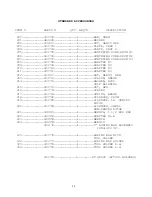
Page 27: ...4 212 433617 1 NUT HEAVY HEX 213 433712 1 SPACER ARBOR 214 433715 1 WASHER ASSY SELF ALIGNING 215 433713 1 NUT HEX 216 433774 1 SPACER 217 433716 1 SPRING ARBOR 218 433782 1 SILENCER DRUM 219 433785 1 SILENCER LG VENTED ROTOR 220 433789 1 SILENCER SMALL NON VENTED ROTOR 221 436410 1 WRENCH 1 1 2 BOX END 222 433963 1 ADAPTER 1 A 223 434558 1 WRENCH 224 434559 1 WRENCH 433172 1 1 BORING BAR ASSEMBLY...

Page 28: ......

Page 29: ...26 ...

Page 30: ...27 ...

Page 31: ...28 ...

Page 32: ...29 ...

Page 33: ...30 ...

Page 34: ...31 ...

Page 35: ...32 ...

Page 36: ......

Page 37: ...33 ...

Page 38: ...N IS IN LIEU OF ALL OTHER WARRANTIES EXPRESS OR IMPLIED INCLUDING BUT NOT LIMITED TO ANY WARRANTIES OF MERCHANTABILITY OR FITNESS FOR A PARTICULAR PURPOSE AND ALL SUCH WARRANTIES ARE HEREBY DISCLAIMED AND EXCLUDED BY SELLER THERE ARE NO WARRANTIES WHICH EXTEND BEYOND THE DESCRIPTION ON THE FACE HEREOF No equipment or parts or accessories shall be shipped by Buyer to Seller without first notifying ...

Reviews: