3-8.
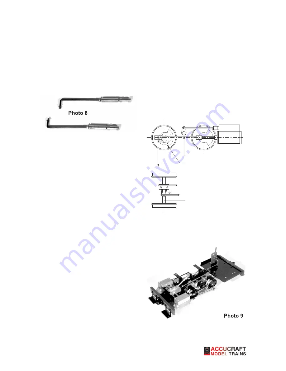
On the short leg of each valve rod (41) are two
small grooves. Snap an e-clip (42) onto each inner
groove. Carefully remove each valve from the valve
blocks and screw them onto the ends of the valve
rods (photo 8). Do not tighten the nut against the
valve at this point, as the valves will have to be ad-
justed later.
Put a little oil on each valve and carefully return it to
its place in the valve block. Insert the other end of
each valve rod through its respective hole in each
rocker arm and secure it with an e-clip (42) in the
outer groove.
3-9.
The eccentrics are the brass discs on the rear
axle. Each has two threaded holes in it with set
screws installed. Loosen the set screws but do not
remove. Slightly tighten one set screw in each ec-
centric, just enough so that when the wheel is rotat-
ed, the eccentric revolves with the axle.
Adjusting the Valve Travel
As with the reversing valve, each of the cylinder
valves has a tiny groove machined into it. In the
valve’s forward-most position, that groove should
be just touching the valve back.
Taking one side at a time, rotate the drivers and
observe the valve’s travels. If the tiny groove trav-
els inside the valve block, screw the valve farther
onto the valve rod. This can be done with the valve
in place – no need to disassemble anything. If the
groove never reaches the block, screw the valve in
the other direction. When the groove finally touches
the block in the valve’s forward-most position, se-
cure the valve on the rod by carefully tightening the
nut against it, making sure that the valve doesn’t
rotate while you are doing so.
Setting the valves
Loosen all of the screws in the eccentrics so that
the eccentrics rotate freely on the axle. Working
with the chassis upside down, rotate the wheels so
that the right-hand side is at rear dead center (i.e.
the piston rod is out as far as it will go – see figure
1). Without rotating the axle, rotate the right-hand
eccentric so that the two holes are equidistant on
either side of the axle when looking straight down
on it. Tighten one screw.
Now follow the same procedure for the other side.
If your work was done correctly, the valves should
now be set and you should have a working chassis.
The finished chassis can be seen in photo 9.
Right side view
Underside view
Figure 1—Setting the valves
Crankpin at
rear dead center
Right eccentric
facing down
Rocker arm straight
up and down
Eccentric holes equally spaced
on either side of axle
4
Summary of Contents for Ruby 0-4-0T Kit
Page 1: ...Ruby 0 4 0T Kit Assembly Instructions...
Page 9: ...7...
Page 10: ...8...
Page 11: ...9...


