3-14.
Place the boiler on the chassis. Screw an
M3-5 phillips-head screw (31) through the deck and
into the rear mounting stud from underneath. Do
not tighten it too much yet.
Fasten the smokebox to the saddle with two M2
x 4 phillips-head screws (40) through the saddle
plate, as per the drawing. This is most easily ac-
complished by inserting your screwdriver through
the smokestack hole for access to the screws. The
screws can be put in position with needle-nose pli-
ers through the smokebox door.
Referring to the drawing, carefully bend the short
leg of the steam pipe until it will smoothly mate with
the thread on the throttle. The two must be well
aligned for a steam-tight fit. Secure the union nut
to the throttle.
3-15.
Place the smokestack washer (53) on the
smokestack nut (52) with the flat side bearing
against the nut. Open the smokebox door, insert the
nut and washer from inside, making sure the cur-
vature of the washer conforms to the curve of the
smokebox, and screw the smokestack (54) partway
on. Tighten the nut, making sure the curvature of
the bottom of the stack conforms to the smokebox.
Secure the nut tightly with pliers.
Drop the exhaust pipe (55) down the stack and
screw it into the valve-block. It need only be finger
tight.
3-16.
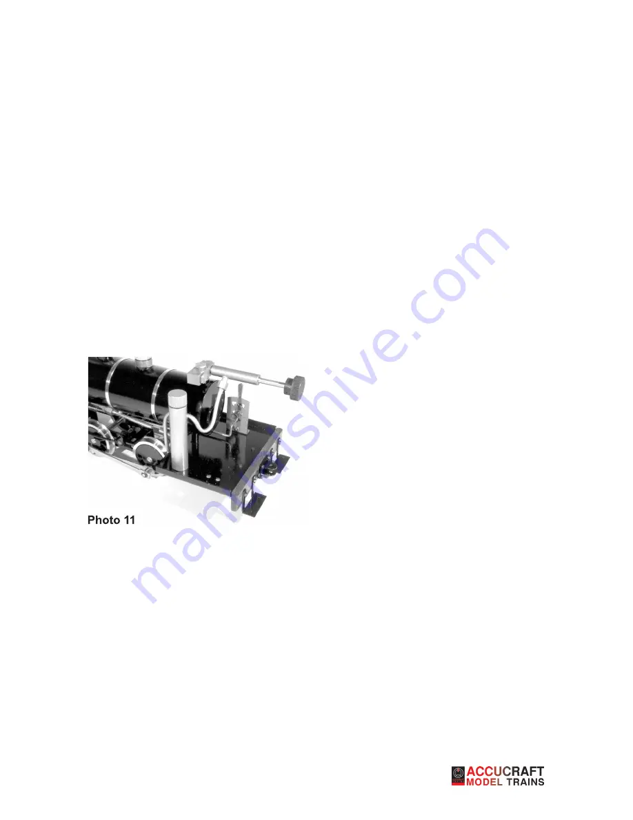
Slip the burner (25) into the flue opening in
the back of the boiler and secure it with an M2 x 4
screw (3). Secure the gas tank (28) to the deck with
one cap nut (29). Slide the jet (26) into the back of
the burner. Carefully and gently bend the copper
gas line until the threaded part of the gas valve lines
up well with the end of the gas line (photo 11). Tight-
en the union nut to the gas valve.
At this point you should have a working locomotive.
Ruby was designed so that the cosmetic compo-
nents (cab and tanks) could be easily modified. The
boiler and chassis comprise the working portion of
the engine. If you’d like, you can try it under steam
now, or you can wait until the tanks, cab and domes
have been applied.
Refer to Sheet 5
5-1.
Take the steam dome base (66) and place it
over the safety valve. The steam dome (65) screws
to the safety-valve bushing, securing the base. The
sand dome (64) merely slips over the filler plug and
is held in place by gravity. Be sure to the remove it
before turning the engine upside down.
5-2.
Lay the side tank support bars (61) across the
brackets, beneath the boiler. Take the right-hand
tank (62) and place it on the bars. Holding every-
thing in place, carefully turn the engine over and
fasten the tank with two M3 x 5 screws (31). Repeat
with the left tank (67).
5-3.
Screw the cab sides (69, 71) to the cab front
as per the drawing, with M2 x 3 screws (72). Then
attach the roof with four M1.6 x 4 screws (73). Rec-
ommend attaching the front two screws first and
then the rear two screws. The cab should slide eas-
ily over the boiler. If it does not, file the inner edges
of the cutout around the boiler until it does.
That completes the Ruby kit. Now go outside and
enjoy many years of steaming.
6
Summary of Contents for Ruby 0-4-0T Kit
Page 1: ...Ruby 0 4 0T Kit Assembly Instructions...
Page 9: ...7...
Page 10: ...8...
Page 11: ...9...


