background image

Acuvim-L Series : L-WEB User manual

www.accuenergy.com

V: 1.0  Revised: Sept. 2019

28

10. Web Interface Readings and Parameter Settings

The L-WEB module supports the HTTPS protocol to allow users to access the meters web 
interface. The user will need to access the L-WEB web interface to configure the module 
and to further use its functions. The web interface allows for remote initial setup of the 
Acuvim L meter.

The L-WEB web interface allows for different user access levels.

10.1 User Access Login

Enter the correct IP address of the module in the search bar of the internet browser to 
access the web interface of the L-WEB.

NOTE: The recommend internet browser for the L-WEB is either Google Chrome or 
Firefox.

The user will be redirected to a login web page where users will have to enter in the 
Access Level and enter appropriate password for that level.

The 

User access level is ideal for users who need only to take readings and view status 

from the meter.

The default password for the User level is 

view.

It is recommended that no more than 5 users are logged in at the same time for this 
level to ensure optimal performance of web interface.

The 

Admin access level is ideal for users who need access to configurations on the 

meter, the web interface and to view readings.

The default password for the Admin level is 

admin.

The L-WEB web interface will only allow one admin to be logged in at a time. If anoth-
er user logs in at this access level, the previous user will be logged out.

Summary of Contents for Acuvim-L Series

Page 1: ...Acuvim L Series Power Meter L WEB User s Manual...

Page 2: ...Copyright 2019 V1 00 This manual may not be altered or reproduced in whole or in part by any means without the ex pressed written consent of Accuenergy...

Page 3: ...e warning of danger or risk during the installation and operation of the meters Electric Shock Symbol Carries information about procedures which must be followed to reduce the risk of electric shock a...

Page 4: ...hod 18 8 1 Direct Connect to a Computer 18 8 2 Direct Connect to Router Switch 21 9 Description of Modbus TCP Protocol 22 9 1 Protocol 22 9 1 1 Data Frame Format 22 9 1 2 Modbus Application Header MBA...

Page 5: ...Q Event Log 43 10 5 About 44 10 6 Settings web page 45 Meter 45 Communication 49 Network 49 Email 51 Time Date 54 Data Log 56 Post Channel 58 AcuCloud 63 BACnet IP 65 SNMP 66 DNP 68 Management 72 Para...

Page 6: ...e L WEB module supports the Modbus TCP protocol When connected to the Acuvim L series meter it is a slave device that can only respond to queries The default value for the Modbus Port is 502 however t...

Page 7: ...w accuenergy com 5 V 1 0 Revised Sept 2019 Chapter 3 Appearance and Dimensions 3 Appearance and Dimensions 90mm Side View 22mm 55 6mm Bottom View Top View 90mm Side View 22mm 55 6mm Bottom View Top Vi...

Page 8: ...eries meter which will expose the sock et 2 Insert the installation clips to the grooves in the Acuvim L series meter and then press the L WEB module lightly to establish a linking between meter and m...

Page 9: ...of IEC 603 7 Top View Script ID Content 1 TX Tranceive Data 2 TX Tranceive Data 3 RX Receive Data 4 n c Not connected 5 n c Not connected 6 RX Receive Data 7 n c Not connected 8 n c Not connected LED_...

Page 10: ...0 Gateway 192 168 1 1 Primary DNS Server 8 8 8 8 Secondary DNS Server 8 8 4 4 Modbus Port 502 HTTP Port 80 This information can be found by using the buttons from the meter display The following is h...

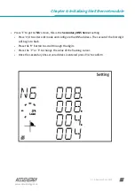
Page 11: ...ameter setting mode The device address page is the first page of the Setting mode It will show the Modbus address of the meter for a second before prompting for the password of the device Press V A bu...

Page 12: ...onfigured as Manual Setting this configuration to Auto will allow the router to assign the meter with an IP address whiles Manual will allow the user to configure the IP address Press the V A button t...

Page 13: ...P address to access the web interface of the module Users can configured the IP address if the DHCP is configured as Manual Press V A to configure the IP address The cursor of the first digit will beg...

Page 14: ...the meters Submask setting Press V A to enter edit mode and configure the sub mask address The cursor of the first digit will begin to flash Press the H button to scroll through the digits and press...

Page 15: ...is is the meters Gateway setting Press V A to enter edit mode and configure the gateway IP address The cursor will begin to flash on the first digit Press the H button to scroll through the digits and...

Page 16: ...er edit mode and configure the DNS address the cursor of the first digit will begin to flash Press the H button to scroll through the digits Press the P or E to change the value of the flashing cursor...

Page 17: ...is the Secondary DNS Server setting Press V A to enter edit mode and configure the DNS address The cursor of the first digit will begin to flash Press the H button to scroll through the digits Press t...

Page 18: ...change the value of the flashing cursor Once the Modbus port setting is configured press V A to confirm Press P to get to N8 this is the network reset setting After making any changes to the NET setti...

Page 19: ...V 1 0 Revised Sept 2019 Chapter 7 Cable 7 Cable An RJ45 cable is needed to connect the meter to the network A shielded twisted pair cable standard 568A or standard 568B is recommended as reference to...

Page 20: ...using a crossover cable standard 568A The L WEB module supports Modbus TCP and HTTPS Functions for this method of connection To connect meter directly to the computer the following can be done using...

Page 21: ...www accuenergy com 19 V 1 0 Revised Sept 2019 Chapter 8 Connection Method Once there click on Change adapter options Once there right click on the Ethernet icon and select properties...

Page 22: ...ersion 4 TCP IP Properties box will pop up Click on Use the following IP address and enter in an IP number so that meter and computer are in the same local network range For example if the meter has I...

Page 23: ...as signed to the meter and then press OK NOTE The meters DHCP setting must be set to Manual in order to connect to the meters web interface using a direct meter to computer connection 8 2 Direct Conne...

Page 24: ...onse to the master device The figure below shows how the Modbus TCP protocol works Modbus Client Modbus Server Request Indication Response Confirmation 9 1 Protocol 9 1 1 Data Frame Format MBAP Header...

Page 25: ...m a master to slave contains additional information which the slave must use to take the action defined by the function code This can include information such as the register addresses the quantity of...

Page 26: ...ifier low Low byte of protocol identifier Length hi High byte of length Length lo Low byte of length Unit identifier Slave address Fun Function code Data start register hi High byte of starting regist...

Page 27: ...The response includes the MBAP header function code quantity of data characters and the data An example response from the meter to read the status of 4 DIs DI1 On DI2 On DI3 On DI4 On is shown below...

Page 28: ...f regs lo 03H 10H 40H 00H 06H An example response is provided to read the time 2006 12 18 14 15 20 Transaction identifier hi Transaction identifier lo Protocol identifier hi Protocol identifier lo Len...

Page 29: ...regs hi Data of regs lo Byte count Value 1 hi Value 1 lo Value 2 hi Value 2 lo 10H 10H 08H 00H 02H 04H 01H F4H 00H 05H Response The normal response to the command request is to retransmit the message...

Page 30: ...nd internet browser for the L WEB is either Google Chrome or Firefox The user will be redirected to a login web page where users will have to enter in the Access Level and enter appropriate password f...

Page 31: ...interface such as Metering About and Settings The dashboard is the first page the user will see once they have entered the correct password for the appropriate access level The dash board is the same...

Page 32: ...L series meter This includes the Line Voltages Phase Voltages Current Neutral Current Ac tive Reactive and Apparent Power Power Factor Frequency Load type and Wiring status The parameters on this pag...

Page 33: ...he energy data for the Acuvim L series meter such as the Active and Reactive energy that is consumed and delivered as well as the Apparent energy per phase This web page also shows the Demand paramete...

Page 34: ...fetime of the meter or from the last time the min max statistics were reset This page also shows the timestamps they were recorded at The parameters in this web page are updated every 10 seconds THD T...

Page 35: ...armonics of the voltage and the current waveform being measured It will display the harmonics of each phase in a graphical and tabular format Select between voltage and current to view their respectiv...

Page 36: ...b page will show the phase angles of the voltage and current waveform being measured which can be used for remote troubleshooting This page provide a visual dia gram of the phase angles with respect t...

Page 37: ...pter 10 Web Interface Readings and Parameter Settings Sequence The Sequence web page will show the positive negative and zero components of the voltage and current waveform being measured The paramete...

Page 38: ...r manual www accuenergy com V 1 0 Revised Sept 2019 36 I O TThe I O web page will display the status of the I O modules that are connected and their DI and DO values The parameters in this web page ar...

Page 39: ...time and energy trend diagram The real time trend log diagram can be selected to show the following parameters phase voltage line voltage cur rent active power reactive power apparent power and power...

Page 40: ...the Time Frame selected Listed below are the time intervals for each possible time frame setting Time Frame Time Intervals Last 10 minutes 5 second 15 seconds 1 minute Last 1 Hour 1 minute Today 15 m...

Page 41: ...time intervals depending on the Time Frame selected The table below displays the time intervals Time Frame Time Intervals Last 1 Hour 1 minute Today 15 minutes 1 hour Yesterday 15 minutes 1 hour Last...

Page 42: ...User manual www accuenergy com V 1 0 Revised Sept 2019 40 Data Preview The data preview allows the user to view the graphical data in tabular form User can also download this data into a csv file for...

Page 43: ...log and Acucloud You can select the between Data Log and AcuCloud by clicking on the tab located on the left side of the web page Once the Data log is selected the log file for will show on the scree...

Page 44: ...estamp of the alarm event Once all 16 alarm events are full the newest alarm event will then wrap around to alarm 1 The parameters in the alarm status web page are updated every 10 seconds SOE Log The...

Page 45: ...dings and Parameter Settings PQ Event Log Note Only Acuvim DL meter and Acuvim EL meter support PQ Event Logs PQ event log will display the power quality issues detected by Acuvim L meter The event lo...

Page 46: ...sers to view the Device Information page This page provides users with information about the Acuvim L series meter and the L WEB module The Device Information contains the model of the Acuvim L meter...

Page 47: ...eter will be monitoring from the modes in the drop down list Current Wiring Select the number of CT s that will be connected to the meter to measure the current PT1 Enter the rated input of the potent...

Page 48: ...Reading Select the mode of the neutral current readings for the meter By default the meter is in calculated mode which will require phase current to calculate the neutral current Configuring the meter...

Page 49: ...1 minute as the window sliding once Fixed Window Demand You select a period time from 1 to 30 minutes which is the period of the calculation The demand updates once as the period time Rolling Window D...

Page 50: ...Acuvim L Series L WEB User manual www accuenergy com V 1 0 Revised Sept 2019 48...

Page 51: ...ter assigned a IP address automatically With this selection the Subnet Mask Gateway and DNS servers will also be automatically assigned NOTE After changing DHCP to Auto check the display of the meter...

Page 52: ...r By default this setting is con figured to 502 The range can be from 2000 to 5999 Proxy Server Enabled Enable this setting so that the L WEB can act as an intermediary to communicate with another ser...

Page 53: ...or sending emails that the user can enable The first mode is Triggered Sending where emails are sent immediately when there is a new alarm SOE or waveform event The second mode is Timed Sending where...

Page 54: ...r name for the SMTP server set above SMTP Password Enter the SMTP user password for the user set above SMTP To Address 1 2 3 Enter up to three recipients that you wish to have the email sent to in SMT...

Page 55: ...Report on the voltage and current harmonics from 2nd to 63rd Sequence Phase Angles Report on the positive negative and zero components of the voltage and current waveform Min Max Report on the maximum...

Page 56: ...can be set through the web interface of the L WEB module The L WEB module also supports the SNTP Simple Network Time Protocol protocol so that the module can update the meter s device clock by synchro...

Page 57: ...the time and date Sync Time Click on Force Update to have the L WEB sync its time with the SNTP serv er SNTP Server 1 2 3 Enter up to 3 SNTP servers in the SNTP Server 1 SNTP Server 2 and SNTP Server...

Page 58: ...rmat for the timestamp can be based on the Local Time UTC Seconds or based on ISO8601 Format Log File Name Format Select the format of the log file name for the data that is logged The format for the...

Page 59: ...to the beginning of the log file if Time Interval Format is selected as the Post File Name Format By default logger1 will be appended to the beginning of the log file Log File Length Select the length...

Page 60: ...will be prompted to reboot the L WEB immediately or later If later is chosen the L WEB must be rebooted from the Man agement page in order for the changes to take effect Post Channel The L WEB suppor...

Page 61: ...the HTTP HTTPs post method is selected HTTP HTTPS URL Enter the URL for the HTTP HTTPS server The URL needs to begin with the prefix http or https HTTP HTTPS Port Enter the port number the server will...

Page 62: ...d in order for user to control the name of the file that will be posted Otherwise file name will be based on the Log File Name Format configuration from the Data Log settings Post File Name User can e...

Page 63: ...server will be listening on FTP Username Enter the username required to log into the FTP server FTP Password Enter the password required to log into the FTP server NOTE The TEST Post Channel 2 button...

Page 64: ...P HTTPS server The URL needs to begin with the prefix http or https HTTP HTTPS Port Enter the port number the server will be listening on HTTP HTTPS Meter ID Enter a name or description for the meter...

Page 65: ...its data to AcuCloud he settings for the AcuCloud post function can be found by clicking on the Settings tab and selecting Communications Select AcuCloud to access the settings to configure the L WEB...

Page 66: ...s on that platform Users must have sufficient access to add devices on their account in order to correctly configure the meter on the software For inquiries on creating your AcuCloud account please co...

Page 67: ...nabled Select Enable to enable the BACnet protocol BACnet Port Enter the BACnet or UDP port number Default port is 47808 Device Instance Enter the instance number for the device in the BACnet system I...

Page 68: ...ports traps to send unsolicited messages to up to four management stations The settings for the SNMP protocol can be found by clicking on the Settings tab and selecting Communications From the communi...

Page 69: ...hould be noti fied when there is an event Report Buffer Size Enter the size of the buffer for the amount of notifications will be stored before being sent to the management station A maximum of 30 not...

Page 70: ...used in the electric utility industry for communication and interop erability among substation computers Remote Terminal Units RTUs Intelligent Electronic Devices e g meters and master stations The se...

Page 71: ...he address number of the master device Source address validation By default the validation is disabled select Enable to enable the destination address validation Supports Unsolicited Reporting Select...

Page 72: ...ain parameters to either class 1 class 2 or class 3 The scale factor is a multiplier that can be applied to a certain parameter when viewing the readings An offset can be applied to the reading The de...

Page 73: ...to all parameters instead of individually configuring each point Once the configuration in the batch modify is complete click on save changes After all DNP settings are complete click on Save Users wi...

Page 74: ...ting is changed if a module reboot is not performed the settings will not be saved to the meter and will go back to its default settings Management Parameter Reset The Management web page allows the u...

Page 75: ...pass words must be 6 characters or more SSH The L WEB module supports the SSH which can be enabled to allow users to remotely log into the meter using the SSH protocol When enabled the status will sh...

Page 76: ...is a diagnostic file on the L WEB module that users can download which can be used to analyze the modules diagnostics NOTE Please send the diagnostic file to Accuenergy Technical Support support accue...

Page 77: ...accuenergy com 75 V 1 0 Revised Sept 2019 Chapter 10 Web Interface Readings and Parameter Settings Network Diagnostic The Network Diagnostic page can be used to monitor the network status of the modu...

Page 78: ...6 In the Host Lookup tab users can utilize the ping function to test the reach ability to other networks User can also use the Connection Test function to test the local network that the module connec...

Page 79: ...firmware update Users can also manually update the firmware by uploading the firmware file The current version of the firmware will be displayed on the Module firmware update page and can also be vie...

Page 80: ...cess to begin the update L WEB will start to reboot when the firmware update is complete Wait for 1 2 minutes to com plete the reboot Remote Update Users can also use the remote firmware server to upd...

Page 81: ...79 V 1 0 Revised Sept 2019 Chapter 10 Web Interface Readings and Parameter Settings If there is a update available users can proceed to download the firmware Once the download is complete the updating...

Page 82: ...cess will take 1 2 minutes to complete After the module reboots users will be able to log back into the web interface When logged in click on the About tab located on the top right corner of the web p...

Page 83: ...77 721 8908 INT 1 416 497 4100 FAX 1 416 497 4130 E marketing accuenergy com ACCUENERGY CANADA INC 2 Lansing Square Suite 700 Toronto ON M2J 4P8 Canada Revision Date September 2019 MAKE ENERGY USAGE S...

Reviews: