Prepared By: Peter Brandt Version: 08 – 20080415
Page
13 of 26
40-6640 Service Manual
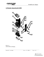
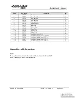
General Assembly Instructions
1.
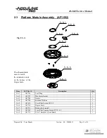
Using three Cross Plate Screws, attach the Bottom Axle (5-6-7) into the bottom of the Degree Scale (5-6-6).
2.
Place the Rotation Platform (5-6-4) onto the Bottom Axle (5-6-7). Place the Gasket (5-6-3) and then
Wave-form Gasket (5-6-2) onto the Bottom Axle. Attach Lock-Ring (5-6-1) using ring pliers to secure all parts.
3.
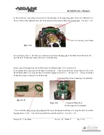
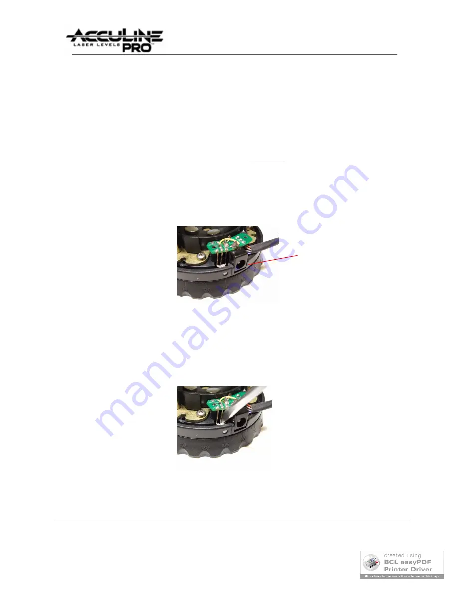
Attach #2 A/C Receptor Circuit Board by first inserting only the tip of indicator bulb into matching hole in
Rotation Platform (5-6-4). Apply a little grease on the indicator bulb before inserting. Then pivot the circuit
board downward so that the A/C plug receptor is matching the slot in the Rotation Platform. Make sure that the
receptor is flush with outside of Base. (See Fig. 2-3-B).
Plug Receptor
Fig. 2-3-B
4.
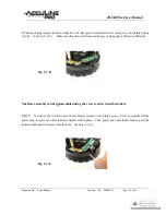
Then gently place 1/8-inch flat head screwdriver between the second and third wire prong and gently leverage
the indicator light forward until it protrudes out from the hole in the Rotation Platform. (See Fig. 2-3-C.)
Fig. 2-3-C

