Prepared By: Peter Brandt Version: 08 – 20080415
Page
14 of 26
40-6640 Service Manual
5.
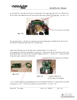
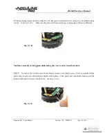
Then push plug receptor down and attach #2 A/C Receptor Circuit Board (5-6-9) using two Cross Plate Screws
(5-6-8). (See Fig. 2-3-D
.
) Make sure that wires are fit into inside groove along edge of Rotation Platform.
Fig. 2-3-D
The Base assembly can be disassembled using the reverse order described above.
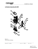
[NOTE: To remove the A/C Receptor Circuit Board, remove Cross Plate Screws (5-6-8) and gently lift the
power plug receptor out while indicator light is still in place. Then gently use a small nail head to push the
indicator light until it releases from the hole. (See Fig
.
2-3-E.)
Fig. 2-3-E

