Prepared By: Peter Brandt Version: 08 – 20080415
Page
6 of 26
40-6640 Service Manual
General Assembly Instructions
1.
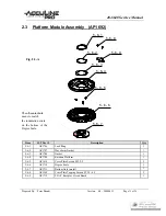
Attach Base Plate Module (5-5) to Platform Module (5-6) using the three Cross Plate Tapping Screws (5-4).
2.
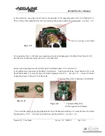
Snap on the Support Seat Ring (5-2) making sure that the inside indentation fits over the protrusion of the
Gimbal ring. Using the four Cross Plate Screws (5-1) attach the Support Seat Ring [together with the Core
Module (5-3)] onto the four Support Pillars (see Fig. 2-2-A) of the Platform Module (5-6). Place Flat Washers
(5-11) on top of Support Pillars so that the Core Module will rest on top of washers. The arm of the pendulum
(bottom piece of Core Module) must be forced through the Locking Ring (see Fig. 2-2-A).
3.
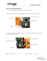
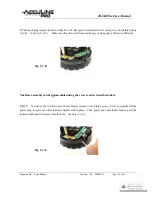
Attach the On-Off Switch Assembly (5-8) [see Fig. 1-1-B for view of complete assembly] by first attaching
the switch portion of assembly using the two Cross Plate Screws (5-7). See Fig. 1-1-C for view of switch
portion attached. This portion of assembly is oriented directly above Crank Shaft (item 5-5-7 of Fig. 2-2-A).
Connecting Circuit Board
Attached here
Connecting Circuit Board
Crank Shaft
Fig. 1-1-B
Fig. 1-1-C
Plug

