background image

Prepared By:    Peter Brandt                                                          Version:    08 – 20080415

Page 

8 of 26

40-6640 Service Manual

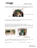
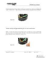
Alarm Rod positioned inside 

Alarm Loop

    Three Screws   
      used to attach 
      Circuit Board

Fig. 1-1-G

The Central Unit assembly can be disassembled using the reverse order described above.   

Summary of Contents for 40-6640

Page 1: ...1 Central Unit Assembly 5 2 0 Component Assembly 9 15 2 1 Core Module Assembly 9 2 2 Base Plate Module Assembly 10 2 3 Platform Module Assembly 12 2 4 Bracket Assembly 15 3 0 Electrical Connections 1...

Page 2: ...Fig 1 A Item JLT Part Description Qty 1 AP1682 Cross Plate Screw M2 5x14 4 2 AP1572 Cross Plate Screw M2 5x10 4 3 AP1681 Back Housing 1 4 AP1683 Front Housing 1 5 AP1684 Central Unit see Sec 1 1 1 6 A...

Page 3: ...connections 1 Connect the battery compartment plug from the Back Housing 3 to the Main Circuit Board See Fig 1 Main Circuit Board Back Housing Plug connected Fig 1 B 2 Connect the plug coming from the...

Page 4: ...r Cross Plate Screws 2 to secure the units Note It may be necessary to use a thin nail placed into the screw holes to center the nuts found inside the instrument so that a straight path is achieved fo...

Page 5: ...ping Screws ST2 9 10 3 5 5 AP1691 Base Plate Module 1 5 6 AP1692 Platform Module 1 5 7 AP1475 Cross Plate Screws M2 5 2 5 8 AP1693 On Off Switch Assembly includes Circuit Boards 3 and 7 Fig 1 1 B 1 5...

Page 6: ...s see Fig 2 2 A of the Platform Module 5 6 Place Flat Washers 5 11 on top of Support Pillars so that the Core Module will rest on top of washers The arm of the pendulum bottom piece of Core Module mus...

Page 7: ...in Section 3 for further help 6 First connect the plug from the A C Receptor Circuit Board item 5 6 9 of section 2 3 to the middle front connection of the Main Circuit Board Then attach the Main Circ...

Page 8: ...ion 08 20080415 Page 8 of 26 40 6640 Service Manual Alarm Rod positioned inside Alarm Loop Three Screws used to attach Circuit Board Fig 1 1 G The Central Unit assembly can be disassembled using the r...

Page 9: ...F CAUTION This module should not be assembled by anyone other than professional service technicians with appropriate equipment Cutting the hairspring wires or any other wires is NOT recommended If rep...

Page 10: ...andt Version 08 20080415 Page 10 of 26 40 6640 Service Manual 2 2 Base Plate Module Assembly AP1691 Fig 2 2 A See parts list on next page 5 5 13 5 5 10 5 5 11 5 5 12 5 5 9 5 5 8 5 5 3 5 5 7 5 5 6 5 5...

Page 11: ...ining holes in Base Plate 5 5 10 using Cross Plate Tapping Screws 5 5 13 3 Insert Crank Shaft 5 5 7 through inside the matching opening in Fixture Support 5 5 9 Make sure that grease is applied to Cra...

Page 12: ...le Item JLT Part Description Qty 5 6 1 AP1706 Lock Ring 1 5 6 2 AP1707 Wave form Gasket 1 5 6 3 AP1708 Gasket 1 5 6 4 AP1709 Rotation Platform 1 5 6 5 AP1616 Cross Plate Screws M2 5 5 3 5 6 6 AP1710 D...

Page 13: ...h 2 A C Receptor Circuit Board by first inserting only the tip of indicator bulb into matching hole in Rotation Platform 5 6 4 Apply a little grease on the indicator bulb before inserting Then pivot t...

Page 14: ...are fit into inside groove along edge of Rotation Platform Fig 2 3 D The Base assembly can be disassembled using the reverse order described above NOTE To remove the A C Receptor Circuit Board remove...

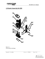
Page 15: ...Peter Brandt Version 08 20080415 Page 15 of 26 40 6640 Service Manual 2 4 Bracket Assembly 40 6356 Fig 2 4 A See Parts List on next page 9 8 9 10 9 4 9 12 9 6 9 7 9 2 9 1 9 5 9 16 9 11 9 14 9 13 9 15...

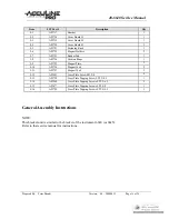
Page 16: ...AP1724 Cushion Rings 1 9 9 AP1725 Magnet Plate 2 9 10 AP1726 Magnet 14x4 2 9 11 AP1727 Magnet 18x4 2 9 12 AP1493 Cross Plate Screw M2 5 8 6 9 13 AP1728 Cross Plate Tapping Screw ST2 2 4 5 1 9 14 AP15...

Page 17: ...l 3 0 Electrical Connections Fig 3 A Fig 3 A 1 Main Circuit Board 4 Alarm Loop Circuit Board outside ring Power Source Batteries 3 Power Switch Circuit Board 7 Connecting Circuit Board 6 Alarm Switch...

Page 18: ...evices have different mechanisms that require calibration there are similarities with optics that are consistent regardless of the leveling mechanism This service manual discusses calibration specific...

Page 19: ...ing within the accuracy specification of the instrument Accuracy specification is the same for the 40 6640 Self leveling Laser 1 8 35 ft 3mm 10m If accuracy does not fall within specification continue...

Page 20: ...e diagram below depending on which laser lines show curvature NOTE The housing needs to be removed For the vertical linearity adjustment the Main Circuit Board will also need to be detached to provide...

Page 21: ...ular to each other and only a small adjustment is needed adjust the hexagonal nut shown Fig 4 2 E using a hexagonal wrench key 3 mm NOTE The nut can be accessed by removing the Plastic Screw see Fig 4...

Page 22: ...3 mm hexagonal wrench key If the lines are not perpendicular to each other or a larger adjustment is needed the housing needs to be removed The Main Circuit Board will also need to be detached to prov...

Page 23: ...ference line AOB If further adjustment is needed use the two screws indicated in the figure below The middle screw needs to be loosened first only by little Then move the horizontal laser line toward...

Page 24: ...board until the alarm rod is centered inside the alarm loop Tighten the screws and attach all housing Fig 5 A Top view of Central Unit Assembly Three Screws Alarm Loop Alarm Rod NOTE If alarm rod need...

Page 25: ...onnected or broken Repair connecting wires 2 Failure to start using A C adapter instrument does not turn on 2 A C Receptor Circuit Board does not work Replace circuit board Connecting wires between ci...

Page 26: ...not aligned properly Adjust and tighten circuit board Connecting wires between circuit boards 1 and 4 are broken Repair connecting wires 6 No buzzer when instrument is tilted beyond tolerance 1 Main...

Reviews: